Axial layered friction stir welding additive forming process for large thin-walled rings

A friction stir and additive forming technology, applied in welding equipment, manufacturing tools, non-electric welding equipment, etc., can solve the problems of ring elongation and strength not meeting design requirements, high energy consumption, and flash formation at welds.

Inactive Publication Date: 2018-11-23
XI AN JIAOTONG UNIV
View PDF7 Cites 2 Cited by
  • Summary
  • Abstract
  • Description
  • Claims
  • Application Information

AI Technical Summary

Problems solved by technology

However, for large rings, since the forming process requires a huge forming force to complete, large-scale rolling and forging equipment is difficult to manufacture, the manufacturing cost is high, and it is difficult to realize it by rolling technology due to the limitation of the forming capacity of the rolling mill and the forming quality of the product. its forming
As the ingot increases, the solidification speed is slow, the material segregation is serious, the grains are coarse and the crack casting defects cannot be completely eliminated in the later rolling and forging process, resulting in the elongation and strength of some rings not meeting the design requirements.
In actual production, it is very easy to have phenomena such as skin clipping, cavity filling, and coarse grains.
Moreover, the successful rolling of large rings is often at the cost of more material loss and higher energy consumption.
In addition, the existing friction stir welding is easy to form defects such as flash, pit and keyhole at the weld
Therefore, the traditional processing methods of large thin-walled rings can no longer meet the market's high-efficiency, energy-saving and material-saving manufacturing requirements, and superior performance.

Method used


Image

  • Axial layered friction stir welding additive forming process for large thin-walled rings
  • Axial layered friction stir welding additive forming process for large thin-walled rings
  • Axial layered friction stir welding additive forming process for large thin-walled rings

Examples


Embodiment Construction

[0022] The present invention will be described in detail below in conjunction with the accompanying drawings.

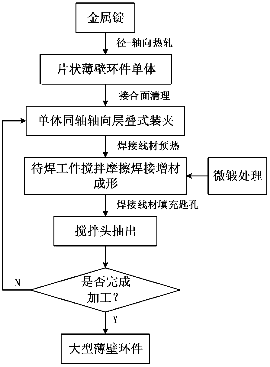
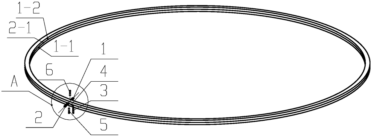
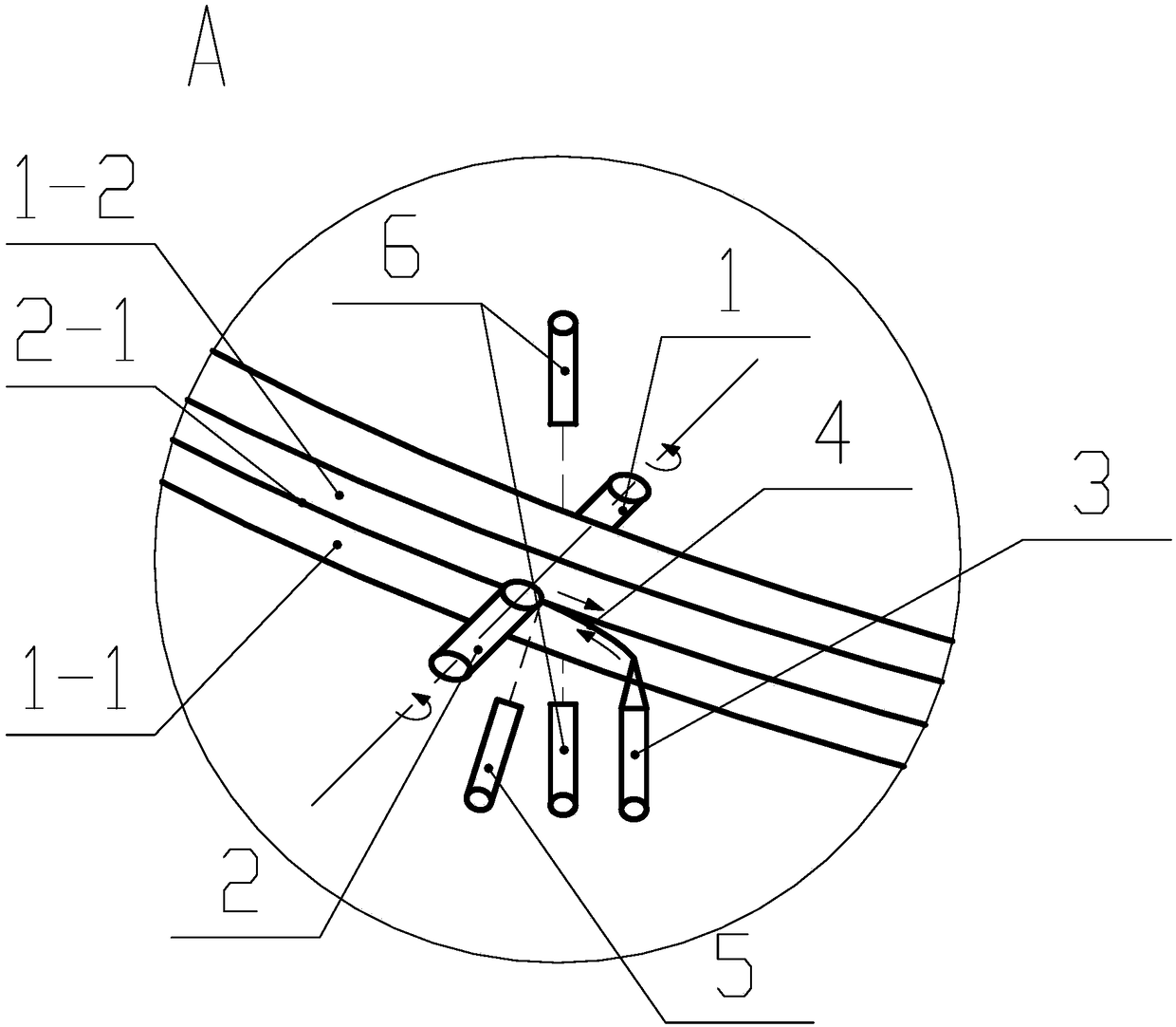
[0023] refer to figure 1 , figure 2 and image 3 , Axial layered friction stir welding additive forming process for large thin-walled rings, including the following steps:

[0024] 1) Sheet-shaped thin-walled rings are individually rolled and formed: the sheet-shaped thin-walled rings are billeted by radial-axial hot rolling technology, and the prepared metal ingots are prepared by blanking, blanking, ring rolling, heat treatment and machining processes Produce flake thin-walled rings;

[0025] 2) Axial stacking type friction stir welding additive forming of sheet-shaped thin-walled ring parts: first, the first sheet-shaped thin-walled ring body 1-1 and the second sheet-shaped thin-walled ring body 1-2 are coaxially stacked and docked The form is clamped on the welding workbench as the workpiece to be welded; then, the welding wire 4 is preheated by the laser he...


PUM


Abstract

Disclosed is an axial stacking type friction-stir welding material adding forming process for a large thin-wall ring part. A sheet-shaped thin-wall ring part single body is prepared first through radial-axial hot rolling technology, then axial stacking type welding forming of the sheet-shaped thin-wall ring part single body is conducted through friction-stir welding material adding forming technology. A welding wire used by welding needs to be preheated by a laser heater, and plasticizing of the welding wire during welding is convenient. Meanwhile, during welding, micro forging treatment needs to be conducted on plasticized metal through an ultrasonic vibration exciter, and the effect that the texture form of the metal forming a weld joint approximately completely forms a welding core is ensured. One week after welding is conducted along the weld joint, a keyhole is filled with the welding wire constantly, meanwhile, a stirring head is drawn out of a workpiece slowly, and thus welding of the first layer of sheet-shaped thin-wall ring part single body is completed. Finally, axial stacking type friction-stir welding material adding forming of the thin-wall ring part is conducted layer by layer. Through the axial stacking type friction-stir welding material adding forming process, the utilization rate of materials is increased significantly, energy consumption is reduced, and the overall performance of the product is improved.

Description

technical field [0001] The invention belongs to the technical field of forming large metal rings, and in particular relates to an axially stacked friction stir welding additive forming process for large thin-walled rings. Background technique [0002] With the rapid development of my country's petrochemical, electric power, shipbuilding, aerospace and equipment manufacturing industries, the demand for ring parts is increasing, with more and more varieties and larger sizes, and the types of materials used are increasingly diversified. For small and medium-sized rings, the more common forming technology is to use ring rolling machines for ring rolling. However, for large rings, since the forming process requires a huge forming force to complete, large-scale rolling and forging equipment is difficult to manufacture, the manufacturing cost is high, and it is difficult to realize it by rolling technology due to the limitation of the forming capacity of the rolling mill and the fo...

Claims


Application Information

Patent Timeline
Patent Type & Authority Patents(China)
IPC IPC(8): B23K20/12B23K20/24
CPCB23K20/122B23K20/24
Inventor 李靖祥张鹏赵升吨董朋赵永强
Owner XI AN JIAOTONG UNIV
Why Eureka
Try Eureka