Electrowetting display device capable of controlling ink movement and preparation method thereof

An electrowetting display and oil column technology, which is applied in the direction of instruments, optics, optical components, etc., can solve the problems of low ink movement efficiency, loss of aperture ratio, and difficult edge smoothing, etc., to achieve a process that is controllable, The effect that the process is easy to achieve

Inactive Publication Date: 2017-07-07
SOUTH CHINA NORMAL UNIVERSITY +2
View PDF5 Cites 15 Cited by
  • Summary
  • Abstract
  • Description
  • Claims
  • Application Information

AI Technical Summary

Problems solved by technology

However, such a structure has the following problems: 1) notch is a fan-shaped ITO electrode structure that has been etched away, and the edges are difficult to make flat, mostly jagged, and it is easy to break down here when pressurized; 2) It affects the hydrophobic in...

Method used


Image

  • Electrowetting display device capable of controlling ink movement and preparation method thereof
  • Electrowetting display device capable of controlling ink movement and preparation method thereof
  • Electrowetting display device capable of controlling ink movement and preparation method thereof

Examples


Embodiment 1

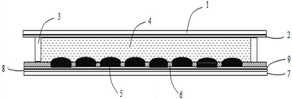
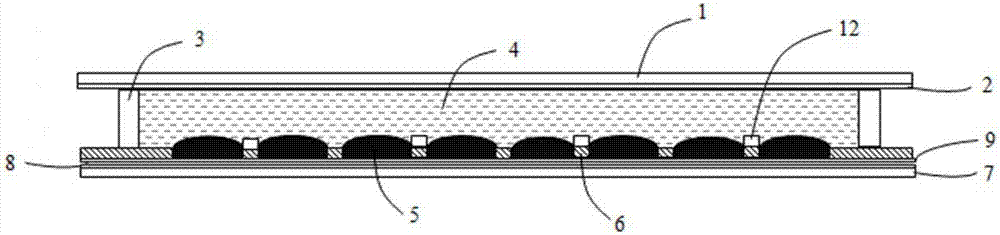
[0047] figure 2 It is a structural schematic diagram of an electrowetting display with an oil control column structure according to the present invention. The main structure is composed of two immiscible polar electrolyte liquids 4 and non-polar liquids 5 filled in the sealed cavity formed by the upper and lower substrates and the two substrates facing each other. composition. The upper substrate is composed of an upper support plate 1 , a first electrode 2 and a sealant 3 , and the lower substrate is composed of a lower support plate 7 , a second electrode 8 , a hydrophobic insulating layer 9 , a pixel wall 6 and an oil control column 12 .

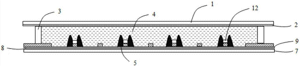
[0048] The oil control column 12 is directly formed above the pixel wall 6 by secondary photolithography, and the shape of the oil control column 12 is a cylindrical or polygonal columnar structure.

[0049] Since the pixel walls form a closed space to accommodate the first fluid, the vertical and horizontal pixel walls will intersect t...

Embodiment 2

[0057] The preparation of electrowetting display has the following two methods

[0058] Method one, such as Figure 7 Shown:

[0059] A1. The preparation method of the conductive layer in the display device has been standardized, so the preparation method of the first electrode 2 and the second electrode 8 in the upper and lower substrates will not be repeated here.

[0060] B1. Coating the solution of the hydrophobic insulating layer 9 on the surface of the lower support plate 7 with the second electrode 8 by methods such as spin coating, blade coating, slit coating, silk screen printing, and flexo printing, and performing thermal curing treatment.

[0061] C1. Apply the photoresist material 6' evenly on the surface of the hydrophobic insulating layer 9. The coating method can be spin coating, blade coating, slit coating, screen printing, roller coating and other methods.

[0062] Before coating, in order to better allow the photoresist material to form a film on the surfac...


PUM


Abstract

The invention, which relates to the technical field of an electrowetting display device, discloses an electrowetting display device capable of controlling ink movement and a preparation method thereof. The display device comprises an upper substrate and a lower substrate. The upper substrate consists of an upper support plate, a first electrode, and a sealant; and the lower substrate includes a lower support plate, a second electrode, a hydrophobic insulating layer and pixel walls and ink control posts are arranged at the pixel walls. In addition, the invention also discloses a preparation method for the electrowetting display device. Because of the ink control posts arranged at the pixel walls, a reliable control way is provided for ink movement. When ink is opened, the ink control posts are compatible with the ink and are repellent to water, so that ink in four pixel grids around the posts is collected towards the posts to realize oriented movement of ink under pressurization and thus the ink movement direction can be controlled. Meanwhile, ink in the pixel grids is reduced because the ink is collected to the posts during the pressurization process, so that the aperture opening ratio of the pixel grid increases.

Description

technical field [0001] The invention relates to the technical field of electrowetting display devices, in particular to an electrowetting display for controlling ink movement and a preparation method thereof. Background technique [0002] The so-called wetting refers to the process in which one fluid on a solid surface is replaced by another fluid. The liquid can spread on the solid surface, and the solid-liquid contact surface tends to expand, that is, the adhesion force of the liquid to the solid surface is greater than its cohesive force, which is wetting. The liquid cannot spread on the solid surface, and the contact surface tends to shrink into a spherical shape, that is, it is not wet, and the non-wet means that the adhesion force of the liquid to the solid surface is less than its cohesive force. Electrowetting (Electrowetting, EW) refers to the phenomenon of changing the wettability of the droplet on the substrate by changing the voltage between the droplet and the ...

Claims


Application Information

Patent Timeline
IPC IPC(8): G02B26/00G09F9/30
CPCG02B26/005G02B2207/115G09F9/30
Inventor 周国富窦盈莹唐彪蒋洪伟吴昊郭媛媛李发宏艾利克斯·汉森·维克多
Owner SOUTH CHINA NORMAL UNIVERSITY
Why Eureka
Try Eureka