Supercharge Your Innovation With Domain-Expert AI Agents!

Current limiting circuit for push-pull output-stage LDO

A push-pull output and current limiting technology, which is applied in the direction of output power conversion device, DC power input conversion to DC power output, electrical components, etc., can solve the problems of increasing design cost and circuit complexity, and achieve simplified circuit structure and realization The effect of detection and protection

Inactive Publication Date: 2017-07-07
UNIV OF ELECTRONIC SCI & TECH OF CHINA +1
View PDF3 Cites 0 Cited by
  • Summary
  • Abstract
  • Description
  • Claims
  • Application Information

AI Technical Summary

Problems solved by technology

Comparators are often used in traditional methods, and the circuit is more complicated, and the circuit design after the overcurrent signal is generated also increases the design cost

Method used


Image

  • Current limiting circuit for push-pull output-stage LDO
  • Current limiting circuit for push-pull output-stage LDO
  • Current limiting circuit for push-pull output-stage LDO

Examples


Embodiment Construction

[0017] The present invention will be described in detail below in conjunction with the accompanying drawings and specific embodiments.

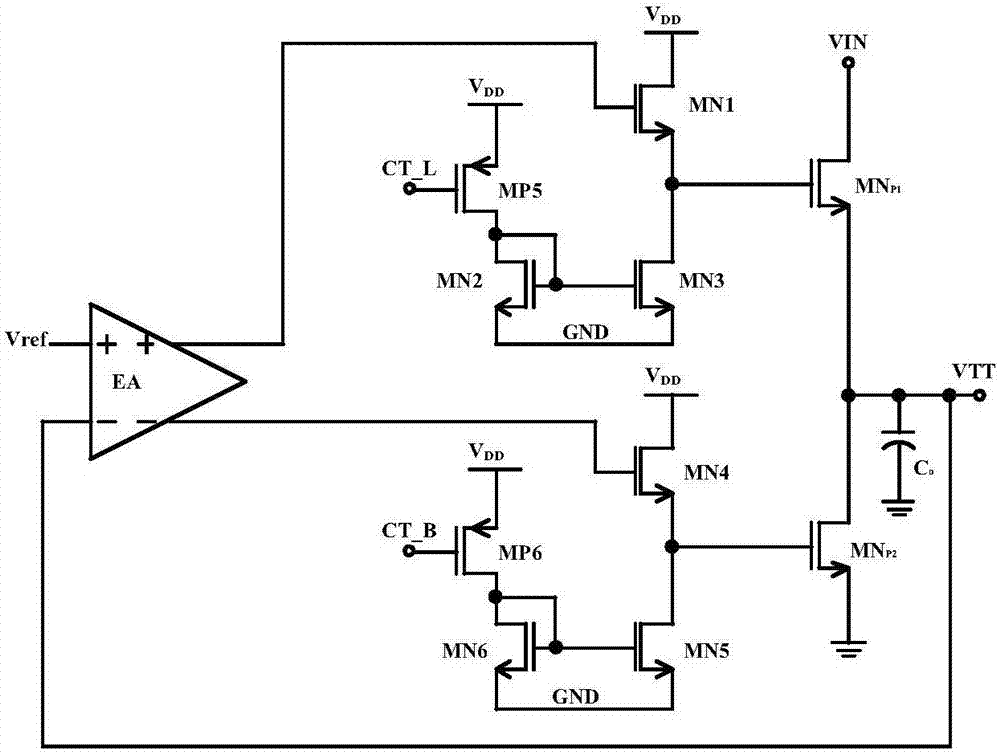
[0018] Such as figure 2 Shown is the LDO circuit topology diagram with push-pull output, which is mainly divided into two parts: error amplifier (Error Amplifier) ​​and power output stage (power stage). The input stage of the error amplifier uses fully differential inputs and passes the resulting differential output signal to the input of the power output stage. figure 2 The LDO circuit shown includes an error amplifier EA, a fifth PMOS transistor MP5, a sixth PMOS transistor MP6, a first NMOS transistor MN1, a second NMOS transistor MN2, a third NMOS transistor MN3, a fourth NMOS transistor MN4, and a fifth NMOS transistor MN5, sixth NMOS tube MN6, capacitor Co, upper power tube NM P1 and lower power tube MN P2 , the middle and upper power tube MN of the output stage P1 and lower power tube MN P2 A push-pull output structure is formed...


PUM


Abstract

The invention provides a current limiting circuit for a push-pull output-stage LDO and belongs to the technical field of electronic circuits. The grid electrode and the source electrode of a first sampling pipe MNP1, SNS are connected with the grid electrode and the source electrode of an upper power tube MNP1, while the drain electrode of the first sampling pipe MNP1, SNS is firstly connected with a first sampling resistor RSNS1 and then connected with the drain electrode of the upper power tube MNP1. The grid electrode and the source electrode of a second sampling pipe MNP2, SNS are connected with the grid electrode and the source electrode of a lower power tube MNP2, while the drain electrode of the second sampling pipe MNP2, SNS is firstly connected with a second sampling resistor RSNS2 and then connected with the drain electrode of the lower power tube MNP2. The first sampling pipe MNP1, SNS samples the current of the upper power tube MNP1. The current flows through the first sampling resistor RSNS1 to produce a voltage drop. The second sampling pipe MNP2, SNS samples the current of the lower power tube MNP2. The current flows through the second sampling resistor RSNS2 to produce a voltage drop. An upper power tube over-current control signal CL _T and a lower power tube over-current control signal CL _B are generated and returned to the push-pull output-stage LDO circuit and then play a role together with the negative feedback loop of the LDO circuit itself. In this way, the output current is stabilized at a preset current value. The over-current damage to the power tubes is avoided. Meanwhile, no comparator is adopted, and the current detection effect and the current protection effect are simultaneously realized.

Description

technical field [0001] The invention belongs to the technical field of electronic circuits, and in particular relates to a current limiting circuit suitable for a push-pull output stage LDO. Background technique [0002] The low-voltage line linear regulator LDO with push-pull output as the output stage is widely used to drive double-rate synchronous dynamic random access memory DDR memory chips. Such as figure 1 Shown is a DDR memory chip with a new power supply method, which can reduce power consumption very well. The power supply voltage VTT is driven by an LDO with a push-pull output stage to increase the output slew rate of the drive stage. During transient switching, it provides a large charging current for the gate capacitance of the power tube and improves the response speed of the power stage to the load. At the same time, the current flowing through the power tube needs to be within a safe range to ensure that the power tube will not be damaged due to excessive c...

Claims


Application Information

Patent Timeline
IPC IPC(8): H02M1/32H02M3/158
CPCH02M1/32H02M3/158
Inventor 明鑫魏秀凌高笛张家豪马亚东王卓张波
Owner UNIV OF ELECTRONIC SCI & TECH OF CHINA
Features
  • R&D
  • Intellectual Property
  • Life Sciences
  • Materials
  • Tech Scout
  • Unparalleled Data Quality
  • Higher Quality Content
  • 60% Fewer Hallucinations
Learn More