
Variable nozzle ring component for effectively preventing blade from clamping stagnation

A nozzle ring and blade technology, applied in engine components, stators, machines/engines, etc., can solve problems such as failure to automatically eliminate stagnation, reduce turbine power efficiency, increase air leakage, etc., to eliminate high temperature stagnation and eliminate stagnation. Lag problem, the effect of improving low-speed performance

Pending Publication Date: 2017-07-11
奕森科技(江苏)有限公司
View PDF7 Cites 3 Cited by
  • Summary
  • Abstract
  • Description
  • Claims
  • Application Information

AI Technical Summary

Problems solved by technology

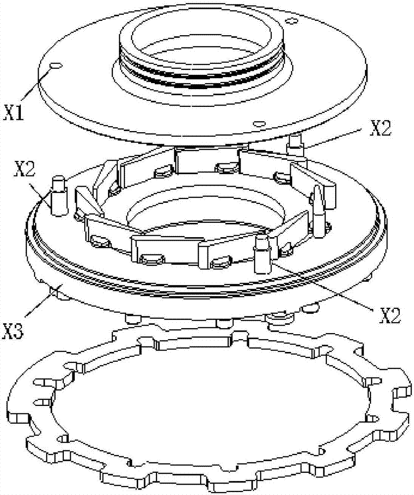
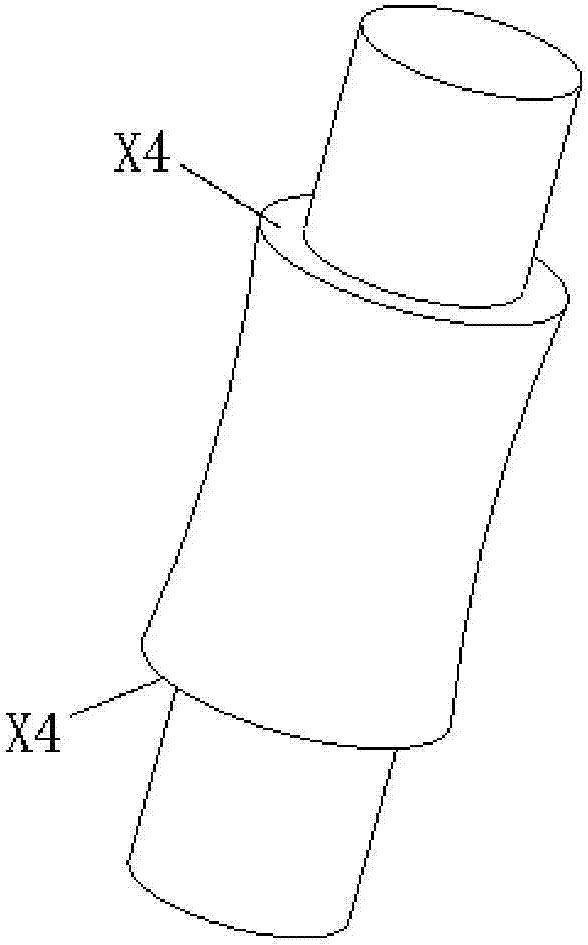
The distance between the two step surfaces X4 minus the height of the blade is the blade clearance. The main disadvantage of this structural design is that when the blade is stuck, since both ends are fixedly assembled, the stuck cannot be automatically eliminated, resulting in pressurization. If the fixed assembly structure at both ends is used, in order to avoid the blades from being stuck during use, the blade clearance will be designed relatively large at the beginning of the design. A larger clearance can reduce the risk of seizure, but it will also increase Air leakage, thereby reducing the work efficiency of the turbine, especially at low speeds

Method used


Image

  • Variable nozzle ring component for effectively preventing blade from clamping stagnation
  • Variable nozzle ring component for effectively preventing blade from clamping stagnation
  • Variable nozzle ring component for effectively preventing blade from clamping stagnation

Examples


Embodiment Construction

[0031] The present invention will now be described in more detail with reference to the accompanying drawings, in which some, but not all embodiments of the invention are shown. Indeed, the invention may be embodied in many different forms and should not be construed as limited to only the embodiments described below; rather, these embodiments are provided so that this disclosure will satisfy applicable legal requirements.

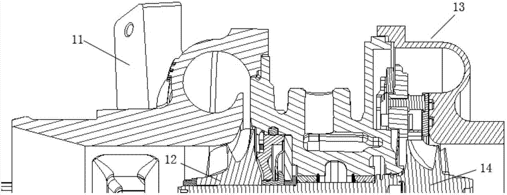
[0032] Such as image 3 As shown, the scroll end of the turbocharger with variable nozzle ring assembly includes a volute 13 and a turbine 14, the turbine 14 is arranged in the volute 13, the annular flow path of the volute 13 receives exhaust gas from the engine, and the ring can be The variable nozzle ring assembly is arranged between the annular flow channel of the volute 13 of the turbocharger and the turbine 14, guides the exhaust gas in the annular flow channel of the volute 13 to blow to the turbine 14; and can adjust the angle of the airflow blowin...


PUM


Abstract

The invention discloses a variable nozzle ring component for effectively preventing a blade from clamping stagnation. The variable nozzle ring component for effectively preventing a blade from clamping stagnation is a turbocharger accessory. A turbine end of the turbocharger comprises a turbine housing, a turbine and the variable nozzle ring component. The variable nozzle ring component comprises a blade guard plate, a spacer pin, the blade, a mounting disk, a rigging pin, a synchronizing ring and an adjusting rocker arm. The blade guard plate is located between the turbine housing and the blade; the spacer pin, the blade and the rigging pin are assembled on the mounting disk, the synchronizing ring is fixed on the mounting disk through the rigging pin, the adjusting rocker arm is connected with the synchronizing ring, and the adjusting rocker arm is assembled with a shaft tail end of the blade. The variable nozzle ring component can reduce the high-temperature clamping stagnation risk of a nozzle blade by means of adjusting a design structure of the spacer pin and the blade guard plate, and simultaneously can reduce a design value of the blade clearance and improve the low-speed performance.

Description

technical field [0001] The invention relates to a turbocharger accessory, in particular to a variable nozzle ring assembly which can effectively prevent blades from sticking. Background technique [0002] A turbocharger is a device used in conjunction with an internal combustion engine to increase the engine's power output by compressing air delivered to the engine's intake for mixing with fuel and combustion in the engine. The turbocharger includes a compressor wheel installed in a compressor housing and a turbine installed in a turbine housing, and there is another intermediate housing connected between the turbine housing and the compressor housing, The intermediate housing is used for bearing installation, cooling and lubrication. Wherein the turbine housing is formed separately from the compressor housing, the turbine housing defines a generally annular flow passage surrounding the turbine, and the turbine assembly includes a nozzle for the flow passage into the turbin...

Claims


Application Information

Patent Timeline
IPC IPC(8): F02B37/24F01D9/04F01D17/16
CPCF01D9/041F01D17/16F02B37/24F05D2240/128F05D2220/40Y02T10/12
Inventor 顾茸蕾刘伟朱明明
Owner 奕森科技(江苏)有限公司
Learn More