
Reflective laser beam shaping device

A laser beam and shaping device technology, applied in optics, optical components, instruments, etc., can solve the problems of low laser quality and low laser output power, achieve uniform distribution of laser power, improve beam quality, and reduce energy loss Effect

Active Publication Date: 2017-07-11
HUAZHONG UNIV OF SCI & TECH
View PDF8 Cites 0 Cited by
  • Summary
  • Abstract
  • Description
  • Claims
  • Application Information

AI Technical Summary

Problems solved by technology

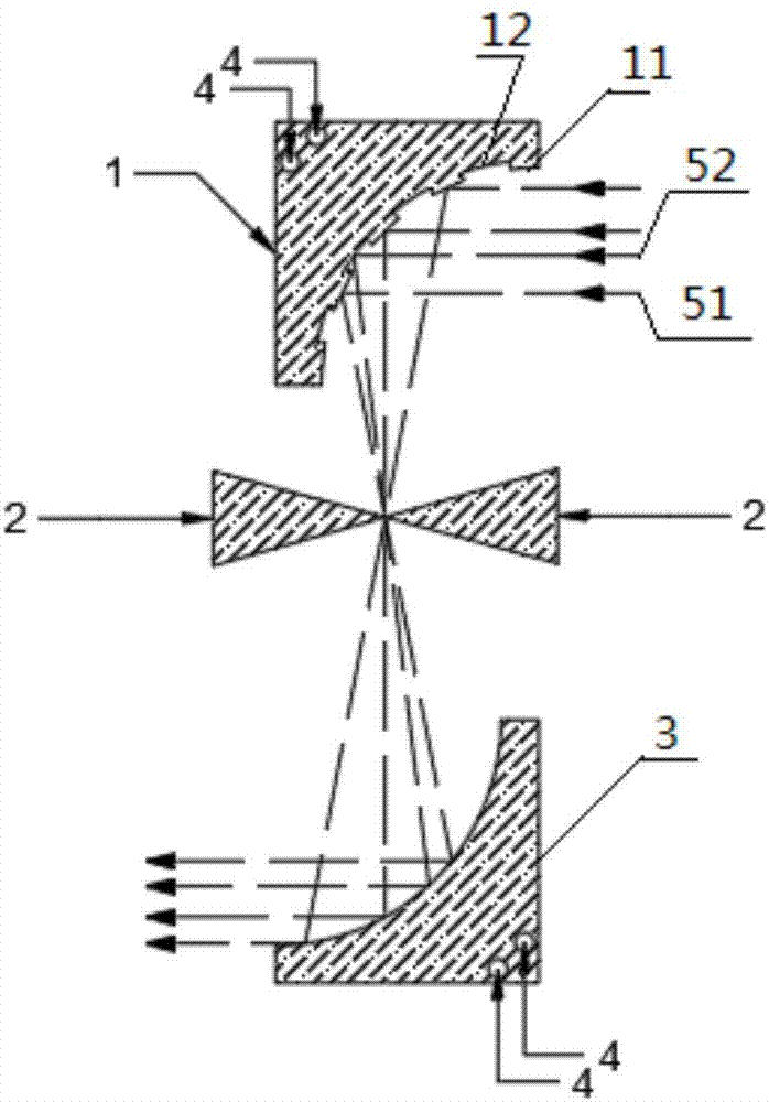
[0004] In view of the above defects or improvement needs of the prior art, the present invention provides a reflective laser beam shaping device, which aims to solve the problem of low laser output power and poor laser quality caused by the existing laser beam shaping device directly using a small hole diaphragm for shaping. high technical issues

Method used


Image

  • Reflective laser beam shaping device
  • Reflective laser beam shaping device
  • Reflective laser beam shaping device

Examples


Embodiment Construction

[0030] In order to make the object, technical solution and advantages of the present invention clearer, the present invention will be further described in detail below in conjunction with the accompanying drawings and embodiments. It should be understood that the specific embodiments described here are only used to explain the present invention, but not to limit the present invention. In addition, the technical features involved in the various embodiments of the present invention described below can be combined with each other as long as they do not constitute a conflict with each other.

[0031] The purpose of the present invention is to convert the high-order mode laser output by the laser into the fundamental mode laser through the laser beam shaping device provided by the present invention, and greatly improve the beam quality of the output laser under the premise of ensuring the laser output power as much as possible.

[0032] The first embodiment of the reflective laser ...


PUM


Abstract

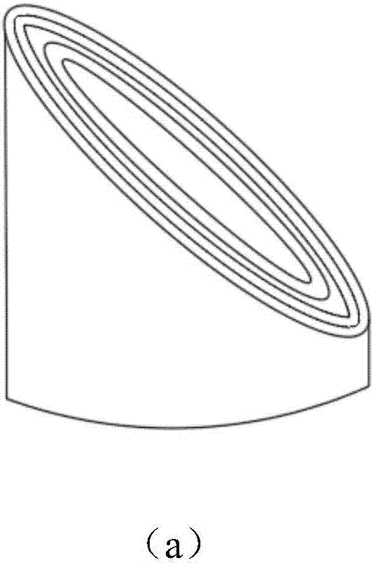
The invention discloses a reflective laser beam shaping device. The reflective laser beam shaping device comprises a phase modulation mirror and a diaphragm, wherein the diaphragm is located at a focus point for outputting first laser of the phase modulation mirror; the phase modulation mirror is used for carrying out phase modulation treatment on incident laser, then focusing the incident laser and outputting the first laser; a phase of a central main peak of the first laser is as same as that of a secondary small peak of the first laser; the diaphragm is used for screening modes of the first laser, enabling the central main peak thereof to pass through the diaphragm and filtering the secondary small peak. The device also comprises a collimating mirror; the collimating mirror is used for compressing the divergence angle of main peak laser beams passing through the diaphragm to obtain laser beams with small divergence angle and single mode. The reflective laser beam shaping device has the characteristics of simple structure and convenience in adjustment; the shaped laser has high power and high quality, and can be applied to multiple laser machining processes such as laser cutting, welding, cladding and perforating and the like.

Description

technical field [0001] The invention belongs to the technical field of laser beam shaping, and more specifically relates to a reflective laser beam shaping device. Background technique [0002] The advantage of laser is good directionality, monochromaticity and coherence. In many occasions of laser applications, such as laser drilling, welding, cutting, and laser medical micro-precision processing, it is desired to obtain high-power output light while the laser output mode is the fundamental mode. Traditional mode selection techniques (such as the use of aperture diaphragms) can improve the quality of the laser output beam, but the use of aperture diaphragms largely limits the mode volume and increases power loss, which limits the power of the output light. [0003] The key to the design of high-power laser devices is how to obtain the highest possible output power while ensuring high beam quality. For large gain region lasers, such as high power cross-flow CO 2 For laser...

Claims


Application Information

Patent Timeline
Patent Type & Authority Applications(China)
IPC IPC(8): G02B27/09
CPCG02B27/0977
Inventor 秦应雄潘新宇丁靓许介铭彭浩唐霞辉
Owner HUAZHONG UNIV OF SCI & TECH
Learn More