Pulping machine for semi-solid pulping, and semi-solid pulping method

A pulping machine and semi-solid technology, which is applied in the field of semi-solid pulping machines, can solve problems affecting production costs, production efficiency and product quality, affecting production tempo and efficiency, and uneven metal liquid temperature. The effect of uniform phase structure, fast speed, and uniform internal crystal structure

Active Publication Date: 2017-07-14
苏州金澄精密铸造有限公司
View PDF13 Cites 3 Cited by
  • Summary
  • Abstract
  • Description
  • Claims
  • Application Information

AI Technical Summary

Problems solved by technology

This kind of pulping method has the disadvantages of fast wear of the stirring rod, high cost, long stirring time, and long cooling time, which affect the production cycle and efficiency. The processed metal liquid has defects such as uneven temperature and uneven crystal structure, which seriously affects production. Cost, production efficiency and product quality

Method used


Image

  • Pulping machine for semi-solid pulping, and semi-solid pulping method
  • Pulping machine for semi-solid pulping, and semi-solid pulping method
  • Pulping machine for semi-solid pulping, and semi-solid pulping method

Examples


Embodiment 1

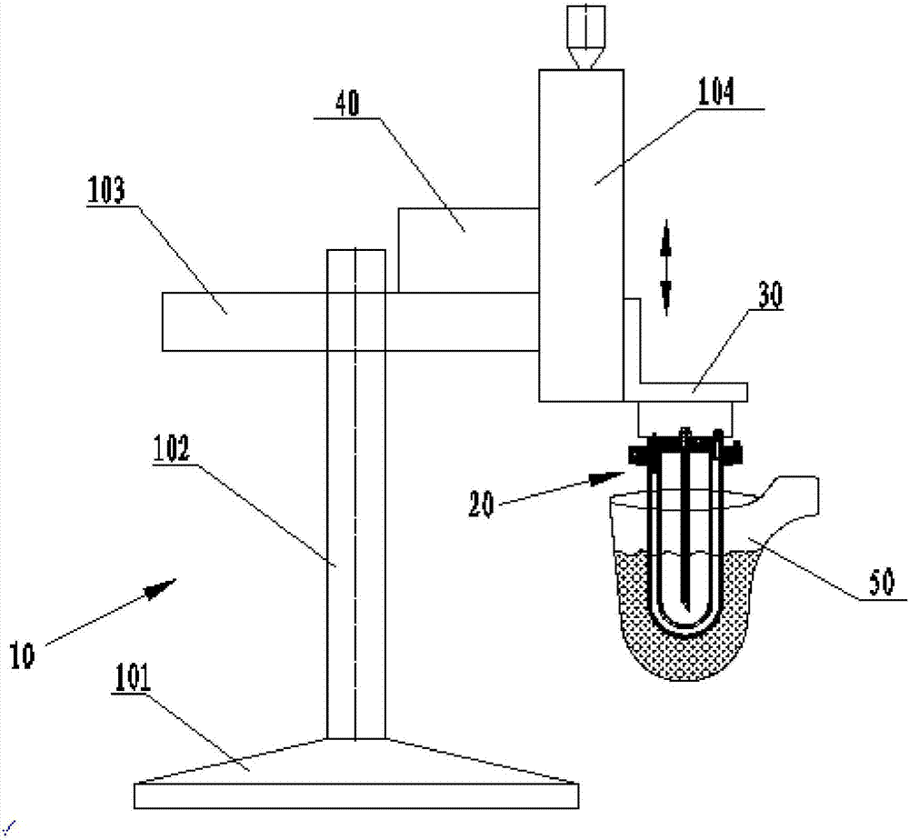
[0046] see figure 1 The shown pulping machine comprises a machine base 10, a support 30 located on the support 10, a pulping head 20 installed on the support 30, and when the soup container 50 is filled with a semi-solid slurry, the system The bottom of the slurry head 20 is inserted into the soup container 50 for slurrying.

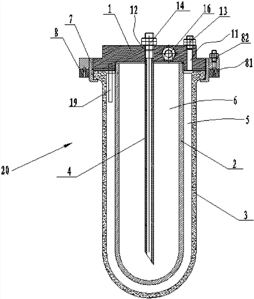
[0047] see figure 2 It is the pulping head 20 used in this embodiment. The pulping head 20 includes a heat exchange inner tank 2, an outer tank 3 sleeved on the outside of the heat exchange inner tank 2, and is fixedly connected to the top of the heat exchange inner tank 2 and the outer tank. 3 the coupling seat 1 on the top, which is fixedly installed on the bracket 30. A closed environment cavity 5 is formed between the heat exchange inner tank 2 , the outer tank 3 and the connection seat 1 , and a closed heat exchange cavity 6 is formed between the heat exchange inner tank 2 and the connection seat 1 .

[0048] Specifically, see figure 2 , Fig...

Embodiment 2

[0079] see Figure 5 The pulper shown with the Figure 6 The pulping head shown is basically consistent with the design concept of embodiment 1, and mainly has the following differences in structure:

[0080] see Figure 5 As shown, the base 10 of the pulping machine includes a base 101, a column 102 erected upwards from the base 101, a beam 103 installed on the top of the column 102 and extending in the horizontal direction through an adjustment seat 105, and the end of the beam 103 is also A support 104 is fixedly provided, and the support 30 is arranged on the support 104 up and down, and the pulping head 20 is fixedly installed on the support 30 .

[0081]Wherein, the column 102 includes a lower column 102a and an upper column 102b that can be slid relative to each other along the vertical direction to realize height adjustment. The seat 105 is connected, the beam 103 is provided with a first handwheel 106 for adjusting the horizontal position of the beam 103 relative t...

Embodiment 3

[0086] see Figure 7 The structure of the machine base 10 of the shown pulping machine is the same as the structure of the machine base 10 in the pulping machine of Embodiment 2, and will not be repeated here. The main difference between it and Embodiment 2 is that the coupling seat 1 on the pulping head 20 is rotatably connected to the support 30 through a rotating shaft (not shown in the figure) extending vertically through the axis line, and the support 30 A rotary motor 60 for driving the coupling base 1 to rotate around the axis of the above-mentioned rotating shaft is also provided.

[0087] see Figure 8 , Figure 9 As shown, in this embodiment, on the pulping head 20, a stirring impeller 9 is fixedly set on the lower body of the outer bladder 3, and the stirring impeller 9 has a plurality of blades distributed evenly along the circumferential direction, so as to Agitation of the slurry is formed during the pulping process.

[0088] In this way, in the pulping machi...


PUM

PropertyMeasurementUnit
pore sizeaaaaaaaaaa
porosityaaaaaaaaaa

Abstract

The invention discloses a pulping machine for semi-solid pulping, and a semi-solid pulping method. The pulping machine comprises a machine seat, a supporting frame arranged on the machine seat, and a pulping head mounted on the supporting frame, wherein the pulping head at least comprises an outer liner used for being inserted in a sizing agent to be prepared; and a plurality of micropores with a ventilating function are densely formed in at least the lower part of the outer liner. In pulping operation, inert gas with certain pressure is introduced into the liner cavity of the outer liner, and the inert gas can uniformly seep into the sizing agent through the micropores which are densely distributed in the liner body of the outer liner, and perform a strong collision reaction and exchange heat with the sizing agent, so that the effects of deslagging, degassing, refining of internal crystal structures of materials, and heat exchange are achieved, and the internal temperature of the sizing agent and the internal crystal structures are uniform. When the pulping machine is used for pulping, automated control can be realized; the pulping machine has multiple advantages of being short in process, high in speed, little in supporting equipment around the pulping machine, low in energy consumption, and the like. The pulping machine is particularly suitable for semi-solid pulping of aluminium alloy solutions, magnesium alloy solutions, and aluminium-magnesium alloy solutions.

Description

technical field [0001] The invention relates to a pulping machine for semi-solid pulping and a semi-solid pulping method. Background technique [0002] Semi-solid metal forming technology is a metal forming technology between solid-state forming and liquid forming. It has the advantages of low flow stress in liquid forming, fast forming speed, and the ability to form parts with complex shapes. extensive attention and research in other fields. In semi-solid metal forming technology, the most critical technology is how to prepare semi-solid slurry with excellent performance. [0003] At present, the commonly used method in the preparation process of the semi-solid slurry is to first use a mechanical stirring rod for stirring, and then cool the stirring rod or add solid materials of the same material. This kind of pulping method has the disadvantages of fast wear of the stirring rod, high cost, long stirring time, and long cooling time, which affect the production cycle and e...

Claims


Application Information

Patent Timeline
Patent Type & Authority Applications(China)
IPC IPC(8): B22D17/00B22D1/00
CPCB22D1/00B22D17/007
Inventor 王万里
Owner 苏州金澄精密铸造有限公司
Why Eureka
Try Eureka