Flexibility pneumatic elevation-type transfer machine and using method thereof

A pneumatic lifting and flexible technology, applied in the direction of cranes, etc., can solve the problem of small lifting coverage area, and achieve the effect of expanding the lifting coverage area, expanding the lifting coverage area, and flexible lifting.

Inactive Publication Date: 2017-07-14
铮孚智能工程(上海)有限公司
View PDF5 Cites 9 Cited by
  • Summary
  • Abstract
  • Description
  • Claims
  • Application Information

AI Technical Summary

Problems solved by technology

[0008] Aiming at the problem of small lifting coverage area in the existing transfer equipment, the present invention provides a flexible pneumatic lifting transfer machine and its use method, which is convenient for moving and handling, has high stability, and increases the lifting coverage compared with the prior art area

Method used


Image

  • Flexibility pneumatic elevation-type transfer machine and using method thereof
  • Flexibility pneumatic elevation-type transfer machine and using method thereof
  • Flexibility pneumatic elevation-type transfer machine and using method thereof

Examples


Embodiment 1

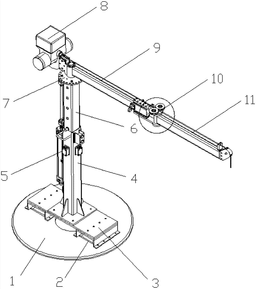
[0041] Such as figure 1 As shown, a flexible pneumatic lifting transfer machine includes a base 1, a column and a cantilever. The base 1 is a disc-shaped structure, which can increase the contact area with the ground and prevent the equipment from moving when transporting materials. There is a risk of rollover; the base 1 is provided with a moving cart hole 2 and a forklift hole 3 to realize the function of moving at any time, and at the same time realize the function of lifting the equipment to walk, and dropping it to use, which is convenient and fast;

[0042] The column is fixed on the base 1; the column includes a column fixed part 4 and a column movable part 6; the column fixed part 4 is fixedly connected to the base 1; the column The movable part 6 is arranged inside the column fixing part 4;

[0043] In order to further improve automation, this embodiment also includes a cylinder; the cylinder body of the cylinder is fixedly connected to the outer wall of the column f...

Embodiment 2

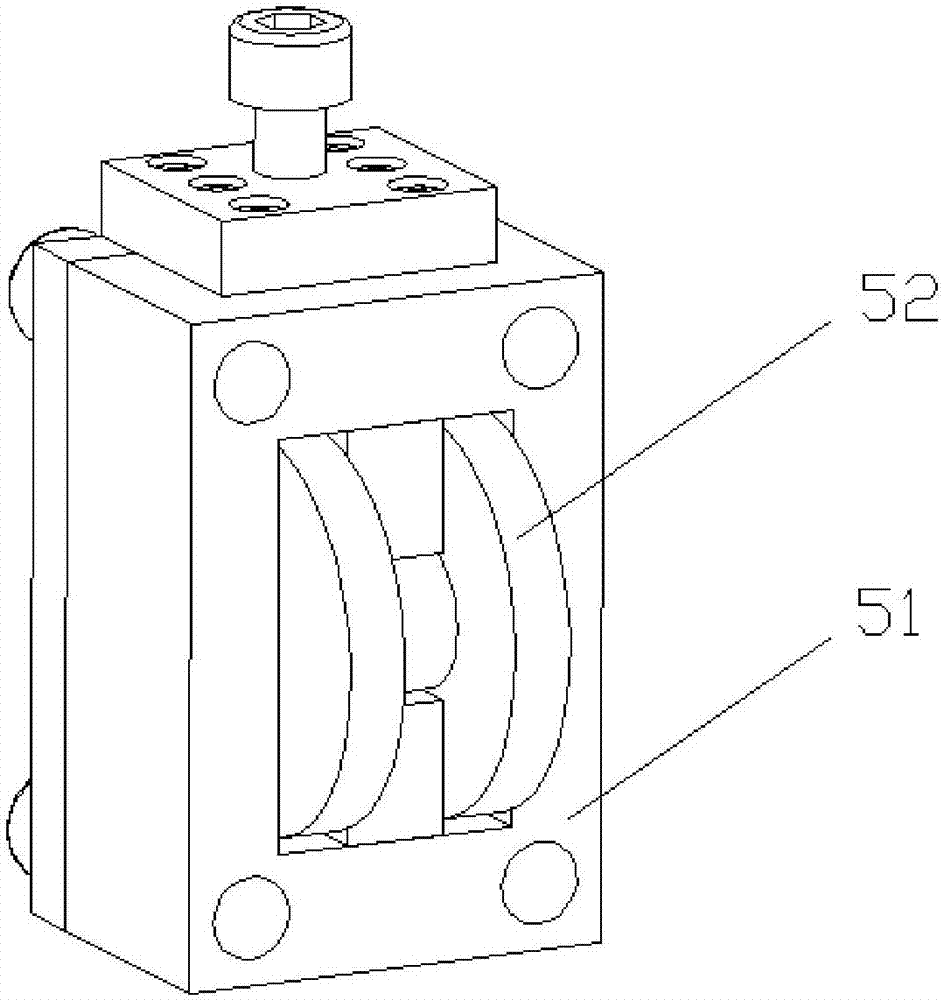
[0059] A flexible pneumatic lifting transfer machine is basically the same as Embodiment 1, the difference is that a guide pulley 5 is arranged between the column fixed part 4 and the column movable part 6; the guide pulley 5 The structure is as figure 2 As shown, it includes a casing 51 and a roller 52 arranged in the casing 51; as figure 1 As shown, the shell 51 is fixed on the outer wall of the column fixing part 4, and an opening is arranged on the outer wall of the column fixing part 4, so that the roller 52 passes through the opening and the column movable part 6 The inner wall contact; the guide pulley 5 can make the movable part of the column 6 go up and down more smoothly, and the stagnation phenomenon will not occur with the fixed part of the column, and the lifting is more flexible.

Embodiment 3

[0061] A flexible pneumatic lifting transfer machine, which is basically the same as Embodiment 1, the difference is that a turntable 7 is provided at the rotatable connection between the cantilever and the column; the turntable 7 is provided with an angle Limiting block; the turntable 7 is pre-set with a plurality of evenly distributed mounting holes along the circumferential direction, and the angle limiting block adjusts the relative position between the cantilever and the column through screws and the mounting holes to achieve different angles limit.


PUM


Abstract

The invention discloses a flexible pneumatic lift-type transfer machine and a use method thereof, which belong to the technical field of mobile handling equipment and solve the problem that the lifting coverage area of ​​the existing transfer equipment is small. The transfer machine of the present invention includes a base, a column and a cantilever, and the column is fixed on the base; the cantilever is rotatably arranged on the top of the column, and also includes a pneumatic balance hoist; the The cantilever includes a long section and a short section; the division point of the long section and the short section is the point where the cantilever is rotatably connected to the column; the pneumatic balance hoist is set on the short section At the end, the steel wire rope in the pneumatic balance hoist protrudes toward the end of the long section along the upper surface of the cantilever. The invention can be easily moved and transported, has high stability, and has the effect of increasing the hoisting coverage area compared with the prior art.

Description

technical field [0001] The invention belongs to the technical field of mobile handling equipment, and in particular relates to a flexible pneumatic lifting transfer machine and its use method. Background technique [0002] my country's manufacturing industry has developed rapidly in recent years, and the manufacturing industry has become an industry with a prominent position in the development of the national economy. With the rapid development of the manufacturing industry, people's demand for material handling is showing a trend of individualization and diversification. The diverse demands of material handling put forward higher requirements for material handling methods in terms of processing accuracy, processing efficiency, comprehensive automation and process integration of manufacturing equipment. Flexible material handling equipment and high reliability and utilization rate, Realizing the rapid response capability of the manufacturing system has become a new topic explo...

Claims


Application Information

Patent Timeline
Patent Type & Authority Applications(China)
IPC IPC(8): B66C23/683B66C23/72
CPCB66C23/70B66C23/72
Inventor 贾海龙卢云杨超王庆庆
Owner 铮孚智能工程(上海)有限公司
Why Eureka
Try Eureka