Mechanical sensor-based intelligent elastic rod type fastener set

A pressure sensor and sensor technology, applied in the direction of instruments, fixed rails, measuring instruments, etc., can solve the problems of difficult fixing of movable rails and inconvenient movement control of movable rails, so as to reduce maintenance difficulty and cost, and avoid rapid failure , fast response effect

Active Publication Date: 2017-07-14
SICHUAN COLLEGE OF ARCHITECTURAL TECH
View PDF5 Cites 4 Cited by
  • Summary
  • Abstract
  • Description
  • Claims
  • Application Information

AI Technical Summary

Problems solved by technology

[0003] my country's track technology is developing towards the direction of seamless track connection, and the most popular solution for traditional turnouts to realize this technology is heart-shaped turnouts and track supplements. For the heart-shaped turnout scheme, there is no need for fixed rails on the outside. Design fasteners for re-fixation, but for rail supplementation using movable rails, additional fasteners need to be designed for fixation
And the phenomenon that the rail cannot rotate after the rail is fixed by the traditional elastic fastener, because of this phenomenon, it will lead to the problem that the movement control of the movable rail is inconvenient or the movable rail is difficult to fix when the movable rail is supplemented.

Method used


Image

  • Mechanical sensor-based intelligent elastic rod type fastener set

Examples


Embodiment 1

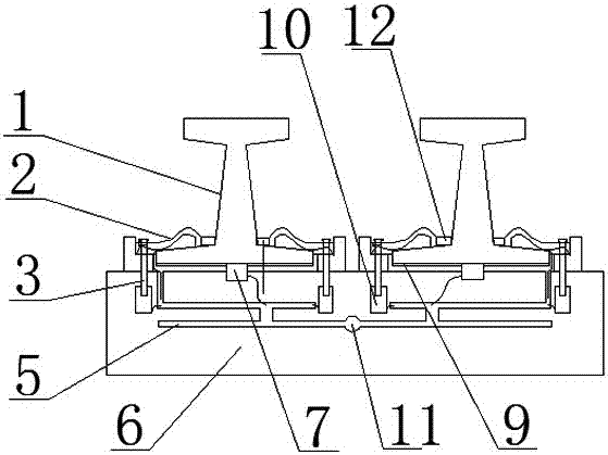
[0019] Such as figure 1 As shown, in this embodiment, a smart elastic fastener group based on a mechanical sensor is suitable for fixing the track at the turnout, including being arranged on both sides of the rail 1, connected with the spike 3 and pressed against the rail 1 The elastic clip 2 on the top, the spike 3 is connected with the base 6 arranged under the rail 1, including the pressure sensor 7 arranged under the rail 1 and capable of sensing the pressure of the rail 1, and the pressure sensor 7 is connected to the circuit through the pressure sensor. The electromagnetic force generator 10 connected; the electromagnetic force generator 10 is connected with the spike 3; the electromagnetic force generator 10 and the pressure sensor 7 are arranged in the base 6; the electromagnetic force generator 10 passes through The main wire is connected to the grid. Described electromagnetic force generator 10 comprises electromagnet and the processor that is electrically connected...

Embodiment 2

[0022] On the basis of the above embodiments, in this embodiment, the base 6 is provided with a circuit groove 5 for installing the connection circuit of the pressure sensor. By accommodating the pressure sensor connection circuit in the circuit slot 5, the influence of environmental factors on the wires can be reduced, the aging of the wires can be delayed, and the risk of wires being run over and damaged by trains can be prevented from being disorderly arranged. In this embodiment, other parts not described are the same as those in the foregoing embodiments, so details are not repeated here.

Embodiment 3

[0024] On the basis of the above-mentioned embodiments, in this embodiment, a main wire hole 11 parallel to the rail 1 and used for installing main wires is provided in the base 6 . In this way, it is convenient to place the main wire in the main wire hole 11 to reduce the aging of the main wire caused by environmental factors, and to avoid the main wire being entangled with the track, resulting in damage to the main wire and leakage of electricity. In this embodiment, other parts not described are the same as those in the foregoing embodiments, so details are not repeated here.


PUM


Abstract

The present invention discloses a mechanical sensor-based intelligent elastic rod type fastener set, comprising elastic rod fasteners provided on the both sides of a rail, connected to spikes and pressed on the rail. The spikes are connected with a base provided below the rail. The mechanical sensor-based intelligent elastic rod type fastener set is characterized by comprising pressure sensors provided under the rail and capable of sensing pressure of the rail, and electromagnetic force generators electrically connected to the pressure sensors via a pressure sensor connection circuit; the electromagnetic force generators are connected with the spikes; the electromagnetic force generators and the pressure sensors are provided in the base; and the electromagnetic force generators are connected with a power grid through a main electric wire. The mechanical sensor-based intelligent elastic rod type fastener set has the beneficial effect that movable tracks can be fixed when the movable tracks are used for track supplementation, and has the advantages of being capable of making a fast response, performing control in real time and reducing the maintenance difficulty and cost, favorable to prolonging the service life of the elastic rod fasteners and the like.

Description

technical field [0001] The invention relates to the field of railway construction, in particular to an intelligent spring type fastener group based on a mechanical sensor. Background technique [0002] Railway technology is gradually developing in the direction of intelligence and digitization. For the same turnout system, the following problems may occur: [0003] my country's track technology is developing towards the direction of seamless track connection, and the most popular solution for traditional turnouts to realize this technology is heart-shaped turnouts and track supplements. For the heart-shaped turnout scheme, there is no need for fixed rails on the outside. Fasteners are designed for re-fixation, but for track supplementation using movable rails, additional fasteners need to be designed for fixing. And the phenomenon that the rail cannot rotate after the rail is fixed by the traditional elastic fastener, because of this phenomenon, it will lead to the problem t...

Claims


Application Information

Patent Timeline
Patent Type & Authority Applications(China)
IPC IPC(8): E01B9/30E01B35/12G01L5/22G01B11/02
CPCE01B9/303E01B35/12E01B2201/04E01B2201/08E01B2203/16G01B11/02G01L5/22
Inventor 王钢尹晓琴彭笑川何威
Owner SICHUAN COLLEGE OF ARCHITECTURAL TECH
Why Eureka
Try Eureka