
Sponge city roof rainwater delayed-shunting and recycling system

A technology of sponge city and recovery system, applied in the field of rainwater delayed diversion recovery system for sponge city roof, can solve the problems of inaccurate airflow effect, manual operation, high processing and manufacturing cost, and achieves simple and novel structure, flexible and convenient use, and easy operation. Effect

Inactive Publication Date: 2017-07-18
NANNING COLLEGE FOR VOCATIONAL TECH
View PDF5 Cites 2 Cited by
  • Summary
  • Abstract
  • Description
  • Claims
  • Application Information

AI Technical Summary

Problems solved by technology

[0004] To sum up, the key to roof rainwater treatment is the disposal of initial rainwater and the removal of impurities and suspended solids. However, at present, roof rainwater collection and reuse projects generally adopt a reuse treatment method similar to domestic sewage, which occupies a large area and requires There are a lot of equipment, and the technology is relatively complicated, some of which require manual operation, resulting in high investment and complicated operation and management. In addition, there are many roof rainwater collection and treatment devices in the prior art, and some of them also have the initial rainwater waste flow. However, many devices are controlled by control units such as solenoid valves. The structure is complex, the manufacturing cost is high, and the maintenance cost is high. It is not suitable for popularization and use. For example, Chinese patent application number 201620860813.2 discloses a rainwater waste The collection device includes a rainwater collection pipe connected to rainwater, a reuse pipe and a water storage tank. A control unit is arranged between the water storage tank and the rainwater collection pipe. The waste flow pipe is connected to the rainwater collection pipe and the reuse pipe through a three-way joint, and the other end of the reuse pipe is connected to the reservoir. On the flow pipe, the recycling electric valve is set on the recycling pipe, the water quality sensor is set on the discarding flow pipe, and a liquid level gauge is installed in the reservoir, and the liquid level gauge is electrically connected to the control unit
Moreover, the current initial rainwater abandonment devices include volumetric waste flow devices and rainfall type waste flow devices. The way of discarding the flow will lead to inaccurate airflow effect, and the dirty rainwater will be recycled

Method used


Image

  • Sponge city roof rainwater delayed-shunting and recycling system
  • Sponge city roof rainwater delayed-shunting and recycling system

Examples


Embodiment 1

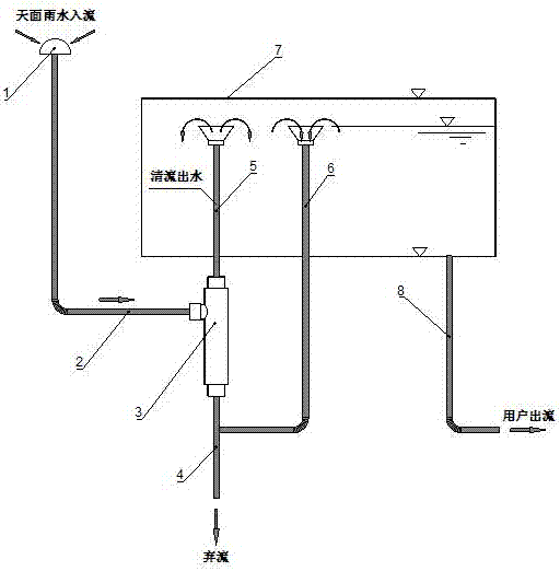
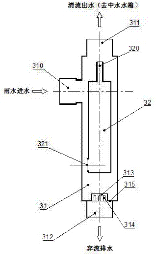
[0027] Such as figure 1 , figure 2 As shown, a sponge city roof rainwater delay diversion recovery system includes a rainwater collector, a rainwater clear flow delay diversion device 3, and a reclaimed water tank 7, and the rainwater clear flow delay diversion device 3 consists of an inner cylinder 32 and an outer cylinder 31 Composition, the inner cylinder 32 is placed inside the outer cylinder 31, the outer cylinder 31 is in the shape of a three-way pipe and is provided with pipe joints, which are respectively the water inlet 310, the clear flow outlet 311, and the discarded flow outlet 312. The discarded flow A baffle 315 is provided on the upper surface of the pipe joint at the drain outlet 312, and a short pipe 313 passing through up and down is provided directly above the baffle 315, and a plurality of flow-discharging holes 314 are provided on the pipe wall of the short pipe 313; The inner cylinder 32 is provided with a long circulation hole 320, and the bottom side ...

Embodiment 2

[0037] The discarded flow hole 314 described in this embodiment is in the shape of a rectangle, preferably a rectangle arranged horizontally, like a rainwater grate, which is evenly stressed, and the water passing area is increased through the rectangle holes of the same size, and the rainwater is in the process of flowing with the waste water. The contact area of ​​the hole wall of the flow hole 314 is reduced, so that the resistance along the process is reduced, and the pressure drop can be further reduced. In Embodiment 2, except for the shape and structure of the jettison hole 314, other devices and structures are the same as Embodiment 1. Of course, according to actual design, the shape of the jettison hole can be selected from other shapes besides rectangle, circle and ellipse, as long as the shape can meet the function of the jettison hole.

[0038] The working principle of the present invention: the rainwater on the sky first passes through the large mesh filters set i...


PUM


Abstract

The invention discloses a sponge city roof rainwater delayed-shunting and recycling system. The sponge city roof rainwater delayed-shunting and recycling system comprises a rainwater collector, a clear rainwater delayed-shunting device and a recycled water tank, wherein the clear rainwater delayed-shunting device consists of an inner barrel and an outer barrel; the outer barrel is shaped as a three-way pipe, and pipe interfaces are arranged at a water inlet, a clear water outlet and a discarded water drain outlet respectively; a partition is arranged on the upper end surface of the pipe interface at the discarded water drain outlet; a short pipe running through up and down is arranged right above the partition; a plurality of discarded water holes are formed in the pipe wall of the short pipe; a long flowing hole is formed in the top end of the inner barrel; a short flowing hole is formed in the side wall of the bottom of the inner barrel. Through arrangement of the clear rainwater delayed-shunting device, initial rainwater is automatically discarded by virtue of high potential of roof rainwater, and after a short period of time delay, later rainwater is recycled, so that arrangement of a lifting water pump and other electrical equipment as well as an electrical control system is not needed, and thus the sponge city roof rainwater delayed-shunting and recycling system is simple in structure.

Description

technical field [0001] The invention relates to the technical field of water supply and drainage for sponge cities, in particular to a time-delayed diversion and recovery system for roof rainwater in sponge cities. Background technique [0002] Sponge city refers to a city that can be like a sponge and has good "elasticity" in terms of adapting to environmental changes and responding to natural disasters. use. At present, the traditional urban drainage mode mainly relies on "grey" facilities such as pipes and pumping stations, and is designed and completed with "rapid discharge" and "end-centralized" control, resulting in increased urban runoff and increased urban drainage burden. , waterlogging is serious, and the phenomenon of "looking at the sea in the city" has seriously affected the urban economic development and the normal living standards of the people. In recent years, sunken green spaces, infiltration ponds, wet ponds, etc. Seepage, but it is difficult to effectiv...

Claims


Application Information

Patent Timeline
Patent Type & Authority Applications(China)
IPC IPC(8): E03B1/04E04D13/04E03F5/10
CPCE03B1/041E03B1/042E03F5/10E03F5/105E04D13/0409E03F2201/10E03B2001/047Y02A20/30
Inventor 全红陈红蒋雪莲陈智圆尤宝庆何际跃
Owner NANNING COLLEGE FOR VOCATIONAL TECH
Learn More