
Laser pretreatment device and treatment method for optical components

A technology of laser pretreatment and optical components, which is applied in laser welding equipment, metal processing equipment, welding equipment, etc., can solve the problems of optical component surface damage, complicated operation, and reduced pretreatment efficiency, so as to improve efficiency and uniform energy density Effect

Inactive Publication Date: 2018-11-06
LASER FUSION RES CENT CHINA ACAD OF ENG PHYSICS
View PDF10 Cites 0 Cited by
  • Summary
  • Abstract
  • Description
  • Claims
  • Application Information

AI Technical Summary

Problems solved by technology

At present, laser pretreatment is one of the effective means to effectively improve the laser damage resistance of optical components, but the circular laser spots usually used are mostly Gaussian distribution, which makes the following problems appear in the pretreatment process: Peak power may cause damage to the surface of optical components; Gaussian circular spot needs to be spliced, which greatly reduces the efficiency of pretreatment; changing the spot size by moving the lens and thus changing the laser energy density makes the operation more complicated, etc.

Method used


Image

  • Laser pretreatment device and treatment method for optical components
  • Laser pretreatment device and treatment method for optical components
  • Laser pretreatment device and treatment method for optical components

Examples


Embodiment Construction

[0033] The present invention will be further described in detail below in conjunction with the accompanying drawings, so that those skilled in the art can implement it with reference to the description.

[0034] It should be understood that terms such as "having", "comprising" and "including" as used herein do not entail the presence or addition of one or more other elements or combinations thereof.

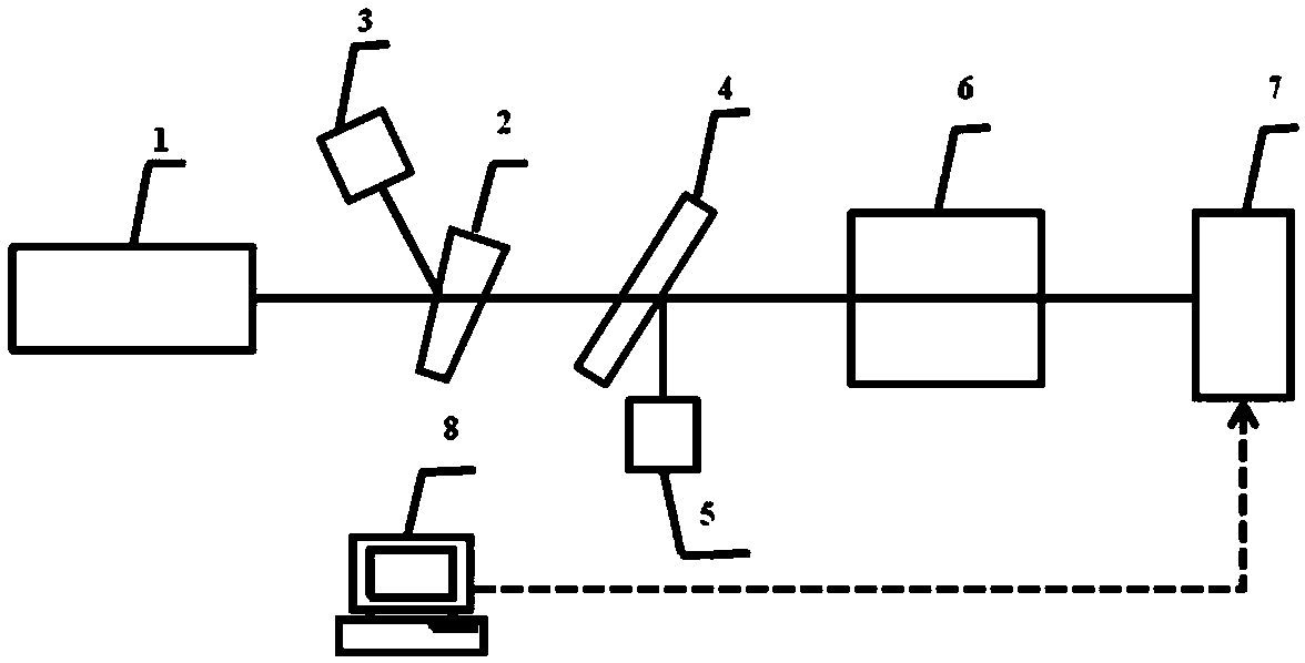
[0035] figure 1 A laser pretreatment device for optical elements of the present invention is shown, including:

[0036] A laser light source 1 for emitting laser light;

[0037] The beam splitting plate 2, the mirror 4, the beam shaping system 6, and the electric translation table 7 for placing the optical elements to be processed are sequentially arranged in the laser transmission direction, and the electric translation table 7 is moved by the control of the control computer 8;

[0038] Among them, the laser light emitted by the laser light source 1 is transmitted to the beam ...


PUM


Abstract

The invention discloses a laser preprocessing device and processing method used for an optical element. The laser preprocessing device comprises a laser light source used for emitting laser as well as a light-splitting chopping plate, a reflecting mirror, a light beam shaping system and an electric translation stage used for placing a to-be-processed optical element are sequentially arranged in the laser transmission direction, wherein laser emitted by the laser light source passes through the light-splitting chopping plate and then is transmitted to the light beam shaping system through the reflecting mirror; the light beam shaping system is used for performing light beam shaping on laser; laser spots which are in Gaussian distribution are shaped into square spots which are uniformly distributed flatly; and finally, the laser is irradiated to the surface of the optical element for performing laser preprocessing on the optical element. According to the laser preprocessing device disclosed by the invention, irradiation energy density of the whole preprocessing process is uniform through the uniform square laser pots which are flatly focused, and dimensions of the spots are easily regulated through a multiplying power switching structure, so that the purpose of regulating energy density of laser which reaches the surface of the optical element is achieved.

Description

technical field [0001] The invention belongs to the field of laser pretreatment of optical materials, and in particular relates to a device and method for laser pretreatment of optical elements. Background technique [0002] The construction of high-power solid-state laser devices requires a huge number and variety of optical components. Taking NIF as an example, the whole device contains 7460 large-aperture optical components (0.5-1.0m), making it not only the largest laser in the world, but also the largest optical system ever. Although there are many technical and scientific challenges in the development of optical components for high-power laser devices, one of the most critical challenges is to eliminate laser-induced damage as much as possible. [0003] Laser pretreatment technology refers to the use of pulsed laser with a certain wavelength to irradiate the optical components with full aperture in a specific process, so as to improve their anti-damage ability. In so...

Claims


Application Information

Patent Timeline
Patent Type & Authority Patents(China)
IPC IPC(8): B23K26/00B23K26/064B23K26/70
CPCB23K26/00B23K26/064B23K26/70
Inventor 蒋一岚栾晓雨王海军廖威陈静张丽娟张传超蒋晓龙白阳袁晓东周海
Owner LASER FUSION RES CENT CHINA ACAD OF ENG PHYSICS
Learn More