Method for improving dynamic wireless charging mean efficiency

A wireless charging, average efficiency technology, applied in circuit devices, electrical components, etc., can solve problems such as low average charging efficiency, low average charging efficiency, and fluctuations in charging efficiency

Inactive Publication Date: 2017-07-21
HUAZHONG UNIV OF SCI & TECH
View PDF3 Cites 13 Cited by
  • Summary
  • Abstract
  • Description
  • Claims
  • Application Information

AI Technical Summary

Problems solved by technology

[0005] Aiming at the problem of low charging average efficiency during wireless dynamic charging, the present invention proposes a method for improving the average efficiency of dynamic wireless charging, which is used in a series wireless charging system, so that the wirel

Method used


Image

  • Method for improving dynamic wireless charging mean efficiency
  • Method for improving dynamic wireless charging mean efficiency
  • Method for improving dynamic wireless charging mean efficiency

Examples


Embodiment 1

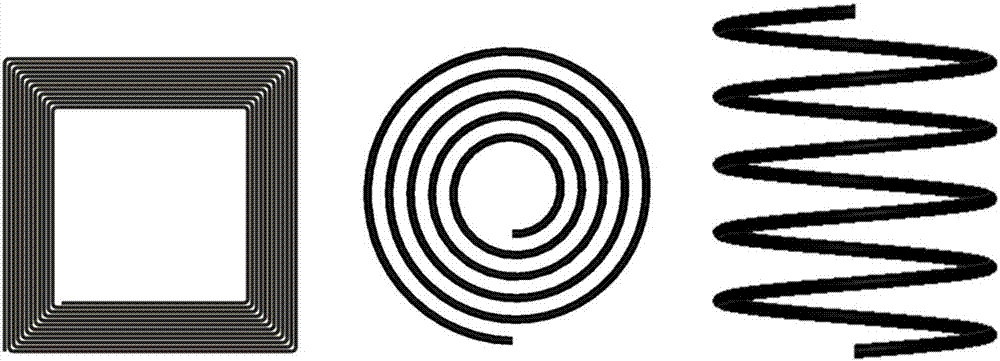
[0097] (1) Wind a transmission coil of appropriate size and specification according to the usage scenario in the actual wireless charging application. Such as figure 2 As shown, it is assumed that 600 strands of 0.1*0.1mm copper Litz wire are used to wind a transmitting and receiving coil with a side length of 50cm and a number of turns of 10, and the magnetic core is fixed on the coil mold to increase the self-inductance and mutual inductance of the coil.

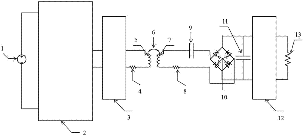
[0098] (2) Assuming that the inductance of the two coils is 200uH at this time, and the internal resistance of the coil is 0.3Ohm, set the output voltage frequency f of the source terminal of the system 0 100kHz, C 2 =12.66nF, the matching circuit of the primary side is a capacitor of 12.66nF connected in series with the transmitting coil.

[0099] (3) if Figure 5 As shown, assuming that the spacing between the coils is 20cm when they are aligned, the mutual inductance is 0.24, and when the lateral offset is 20cm, the...

Embodiment 2

[0104] (1) Wind a transmission coil of appropriate size and specification according to the usage scenario in the actual wireless charging application. Such as figure 2 As shown, it is assumed that 400 strands of 0.1*0.1mm copper Litz wire are used to wind a transmitting and receiving coil with a side length of 40cm and a number of turns of 15, and the magnetic core is fixed on the coil mold to increase the self-inductance and mutual inductance of the coil.

[0105] (2) Assuming that the inductance of the two coils is 250uH at this time, and the internal resistance of the coil is 0.3Ohm, set the output voltage frequency f of the system source 0 80kHz, C 2 =15.83nF, the matching circuit of the primary side is a capacitor of 15.83nF connected in series with the transmitting coil.

[0106] (3) if Figure 5 As shown, assuming that the spacing between the coils is 15cm and the mutual inductance is 0.3, when the horizontal offset of the coils is 20cm, the mutual inductance betwee...

Embodiment 3

[0111] (1) Wind a transmission coil of appropriate size and specification according to the usage scenario in the actual wireless charging application. Such as figure 2 As shown, it is assumed that 500 strands of 0.1*0.1mm copper Litz wire are used to wind a transmitting and receiving coil with a side length of 45cm and a number of turns of 20, and the magnetic core is fixed on the coil mold to increase the self-inductance and mutual inductance of the coil.

[0112] (2) Assuming that the inductance of the two coils is 150uH at this time, and the internal resistance of the coil is 0.4Ohm, set the output voltage frequency f of the system source 0 150kHz, C 2 =7.5nF, the matching circuit on the primary side is a 7.5nF capacitor connected in series with the transmitting coil.

[0113] (3) if Figure 5 As shown, assuming that the spacing between the coils is 20cm and the mutual inductance is 0.25, when the angle of the receiving coil is offset by 40 degrees, the mutual inductanc...


PUM

PropertyMeasurementUnit
Inductanceaaaaaaaaaa

Abstract

The invention discloses a method for improving the dynamic wireless charging mean efficiency, and the method comprises the steps: the winding of a transmission coil, the measurement of parameters of the transmission coil, the precise measurement of the offset coupling efficiency of the coil, the calculation of theoretical input resistance, and the determining of the type of a front-end chopper circuit and the duty ratio of a battery. Aiming at a common serial dynamic resonance wireless charging system, the method sets theoretical parameters according to the parameters of an actual transmission circuit. Because the method employs the specific chopper circuit to achieve the impedance conversion, the method can meet the charging requirements under the conditions of various types of battery internal resistance, and enlarges the application range of the actual system. The method weakens the impact on the wireless charging efficiency from the change of a coupling coefficient of the position change of the coil during the dynamic charging of the serial dynamic resonance wireless charging system, guarantees the maximum mean efficiency of dynamic charging to the greatest extent, and improves the transmission characteristics of the wireless charging system. According to the invention, a rectification circuit and the chopper circuit in the method are common circuits, and the number of parts of the system is small. The method is high in practicality.

Description

technical field [0001] The invention relates to the field of wireless energy transmission, and relates to a method for improving the average efficiency of dynamic wireless charging. Background technique [0002] Traditional power transmission is realized by wire, but due to factors such as line aging and transmission loss, the reliability, safety and efficiency of the power supply process are greatly reduced. At the same time, some special occasions such as mines and seabeds, as well as the crossing of power lines for a large number of electrical equipment in life, limit the scope and practical use of wired power supply. As early as the middle and late 19th century, wireless power transfer technology was proposed by Nikola Tesla. After a long period of scientific and technological development, in 2007, Professor Marin Soljashik of the Massachusetts Institute of Technology and his research team made a major breakthrough in the field of magnetically coupled resonant wireless ...

Claims


Application Information

Patent Timeline
IPC IPC(8): H02J50/12
Inventor 刘明海王圣明胡朝阳荣灿灿路聪慧
Owner HUAZHONG UNIV OF SCI & TECH
Why Eureka
Try Eureka