
Tool bit conveying and clamping system for diamond thin-walled drill laser welding machine

A laser welding and thin-wall drilling technology, applied in laser welding equipment, welding equipment, metal processing and other directions, can solve the problems of implementation and promotion of laser welding technology, and achieve great market prospects and market value, great labor intensity, accurate positioning

Active Publication Date: 2017-07-28
郑州金海威科技实业有限公司
View PDF9 Cites 1 Cited by
  • Summary
  • Abstract
  • Description
  • Claims
  • Application Information

AI Technical Summary

Problems solved by technology

[0003] The laser welding technology of diamond thin-walled drills is a main research direction and means for improving the overall performance of diamond thin-walled drills at this stage. In the prior art, there are few disclosures of laser welding technology in diamond welding automation equipment, and relatively many Only the research papers and the development direction of laser welding technology lead to great constraints on the implementation and promotion of laser welding technology

Method used


Image

  • Tool bit conveying and clamping system for diamond thin-walled drill laser welding machine
  • Tool bit conveying and clamping system for diamond thin-walled drill laser welding machine
  • Tool bit conveying and clamping system for diamond thin-walled drill laser welding machine

Examples


Embodiment 1

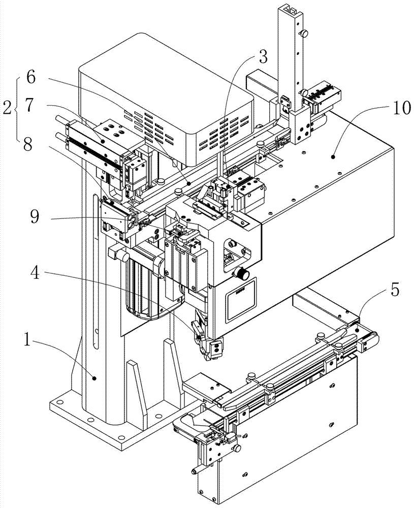
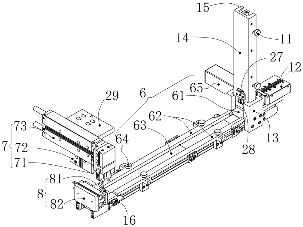
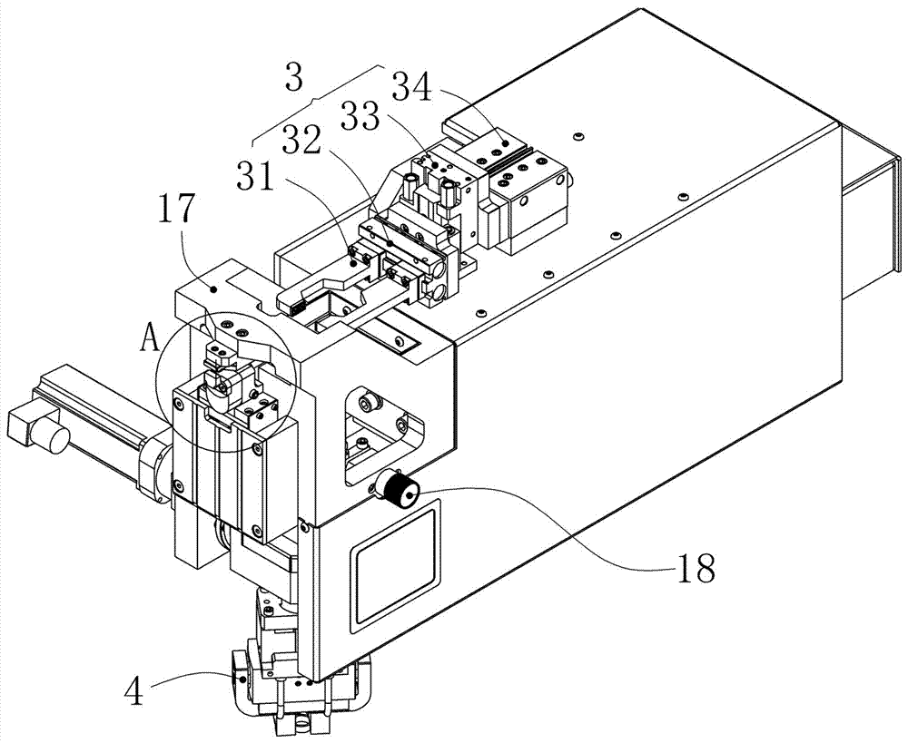
[0026] Embodiment 1: see Figure 1 to Figure 6 , a diamond thin-wall drill laser welding machine cutter head transmission and clamping system, including a support frame 1, a single-tooth cutter head transmission device 2 fixed on the support frame 1, a single-tooth cutter head buffer device 3, and a horizontal slide table 10 , the front end of the horizontal slide table 10 is provided with a single-toothed cutter head clamping device 9 and a ring-toothed cutter head clamping device 4, and a ring-toothed cutter head conveying device 5 is provided below it; the single-toothed cutter head conveying device 2 will The single-tooth cutter head is conveyed and transferred to the single-tooth cutter head buffer station, and the single-tooth cutter head clamping device 9 clamps and sends the single-tooth cutter head buffered on the buffer device 3 to the welding station; The ring-toothed cutter head conveying device 5 conveys the ring-toothed cutter head 20 to the ring-toothed cutter h...


PUM


Abstract

The invention discloses a tool bit conveying and clamping system for a diamond thin-walled drill laser welding machine. The tool bit conveying and clamping system comprises a supporting frame, a single-tooth tool bit conveying device, a single-tooth tool bit temporarily-storing device and a horizontal sliding table, wherein the single-tooth tool bit conveying device and the single-tooth tool bit temporarily-storing device are fixed to the supporting frame correspondingly. A single-tooth tool bit clamping device and a ring-tooth tool bit clamping device are arranged at the front end of the horizontal sliding table, and a ring-tooth tool bit conveying device is arranged below the horizontal sliding table. The single-tooth tool bit conveying device is used for conveying a single-tooth tool bit and transferring the single-tooth tool bit to a single-tooth tool bit temporarily-storing station. The single-tooth tool bit clamping device is used for clamping and conveying the single-tooth tool bit temporarily stored on the temporarily-storing device to a welding station. The ring-tooth conveying device is used for conveying a ring-tooth tool bit to a ring-tooth tool bit clamping station, and the ring-tooth clamping device is used for clamping and conveying the ring-tooth tool bit to the welding station. According to the tool bit conveying and clamping system for the diamond thin-walled drill laser welding machine, due to the structural design of the single-tooth tool bit conveying device and the ring-tooth tool bit conveying device, automatic conveying, grabbing and clamping of two kinds of different tool bits are achieved, and a good foundation is provided for the subsequent welding process.

Description

technical field [0001] The invention relates to the technical field of diamond thin-wall drill welding, in particular to a cutter head transmission and clamping system of a diamond thin-wall drill laser welding machine. Background technique [0002] The diamond thin-walled drill bit is a new type of drilling tool, which consists of a base body and a cutter head. It has the characteristics of accurate drilling size, high speed, no damage to the surrounding material and no need for subsequent processes. It is mainly used to drill small holes and large diameter holes in various building materials, especially for the laying of wires or pipes during engineering renovation or building reconstruction, and it is also essential for deep cutting of concrete and cutting large diameter holes tool. [0003] The laser welding technology of diamond thin-walled drills is a main research direction and means for improving the overall performance of diamond thin-walled drills at this stage. I...

Claims


Application Information

Patent Timeline
Patent Type & Authority Applications(China)
IPC IPC(8): B23K26/70B23K26/21B23K101/20
CPCB23K26/21B23K26/702B23K2101/20
Inventor 海小平吴志峰于化龙耿泽中王建国张东林王卫国
Owner 郑州金海威科技实业有限公司
Learn More