Centralized heating system with industrial waste heat integrated utilization function and using method thereof

An industrial waste heat and central heating technology, applied in hot water central heating systems, heating systems, household heating, etc., can solve the problem of unreasonable heat transfer distance, unreasonable heat exchange process, primary network return water temperature, etc. Reduce to 30 ℃ and other issues

Active Publication Date: 2017-07-28
TSINGHUA UNIV
View PDF10 Cites 14 Cited by
  • Summary
  • Abstract
  • Description
  • Claims
  • Application Information

AI Technical Summary

Problems solved by technology

[0004] 1. The heat exchange process in the factory is unreasonable
The existing waste heat recovery technology usually only considers the waste heat of circulating water in power plants and other industries. The heat exchange heat source is too single, and the circulating water is often sent directly to the terminal unit or the heat is directly taken by the heat pump and sent to the end user. The concept of cascade utilization
In addition, waste heat in the process other than circulating water, such as constant top oil and gas in the refinery, mid-section reflux and other waste heat above 50°C, was not considered, and the effect of the heat extraction link was not optimized.
[0005] 2. The temperature difference between supply and return water in the heating network is small, the investment in the pipe network is large, and long-distance transportation is difficult
At the same time, although the heat source uses heat pumps to extract the waste heat from circulating water, the water flow in the heating network is huge and cannot be transported over long distances
[0006] 3. The end is not properly configured, and there is heat loss in the heat exchange process
However, in fact, the user-side secondary network water supply demand temperature is often below 60°C, and the primary network water at 130°C is directly exchanged with the secondary network water, wasting the driving force of the primary network water supply
At the same time, in this patent, the users of the secondary network need to meet the reasonable ratio of different temperature ranges. Only when the heat supply of the primary network water at 40°C to 30°C matches the load of the floor heating user, can it be possible to return the water to the primary network. temperature down to 30°C
Therefore, the return water temperature of the primary network is greatly affected by the demand of the end user side during actual operation.
[0007] 4. The electric heat pump consumes a lot of power and has high operating costs
The existing waste heat heating method is to directly extract low-grade industrial waste heat through the electric heat pump, but the electric heat pump runs for a long time, consumes a lot of power, and the electricity price is expensive. Although it is energy-saving and environmentally friendly, the economy is usually poor
[0008] 5. The scale of waste heat heating is small, which cannot meet the needs of urban-scale central heating
Due to the irrationality of heat acquisition and the limitation of transmission distance, the existing waste heat heating technology often focuses on the heating of close-distance users such as factory family areas, and cannot solve the problem of large-scale urban industrial waste heat centralized heating

Method used


Image

  • Centralized heating system with industrial waste heat integrated utilization function and using method thereof
  • Centralized heating system with industrial waste heat integrated utilization function and using method thereof
  • Centralized heating system with industrial waste heat integrated utilization function and using method thereof

Examples


Embodiment 1

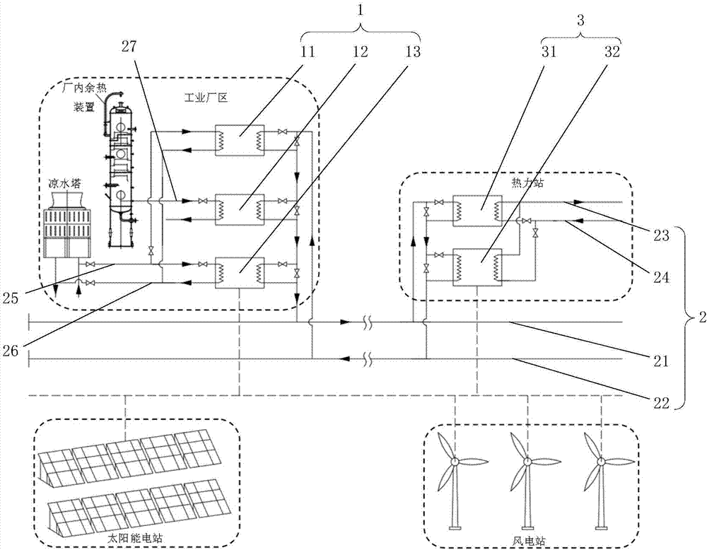
[0064] Such as figure 1 As shown, this embodiment provides a centralized heating system for integrated utilization of industrial waste heat, which includes an industrial waste heat collection subsystem 1 , a heat transfer network 2 and a terminal heat utilization subsystem 3 . Among them, the industrial waste heat collection subsystem 1 includes a circulating water heat exchanger 11, a low-temperature waste heat material heat exchanger 12, and an in-plant electric heat pump 13; Network water supply pipeline 23, secondary network return water pipeline 24, circulating water supply pipeline 25, circulating water return pipeline 26 and low-temperature waste heat logistics pipeline 27; terminal heat utilization subsystem 3 includes heat network water heat exchanger 31 and terminal electric heat pump 32.

[0065] The inlet of the heat release side of the circulating water heat exchanger 11 is connected to the return water pipe 22 of the primary network, and the outlet is connected ...

Embodiment 2

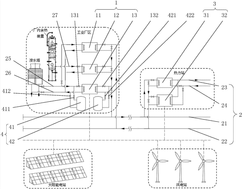
[0072] Such as figure 2As shown, this embodiment provides a central heating system that integrates and utilizes industrial waste heat, and its structure is basically the same as that of Embodiment 1, but the central heating system in this embodiment also includes a thermal storage subsystem 4 . The heat storage subsystem 4 includes a circulating water heat storage tank 41 and a primary grid heat storage tank 42 in the plant. The tank top interface and the tank bottom interface of the circulating water heat storage tank 41 are respectively connected to the inlet and outlet of the heat-taking side of the electric heat pump 13 in the plant. The tank top interface and the tank bottom interface of the primary network heat storage tank 42 in the plant are respectively connected with the outlet and inlet of the heat release side of the electric heat pump 13 in the plant; The first factory valve 131 and the second factory valve 132 are respectively set, and the tank top interface and...

Embodiment 3

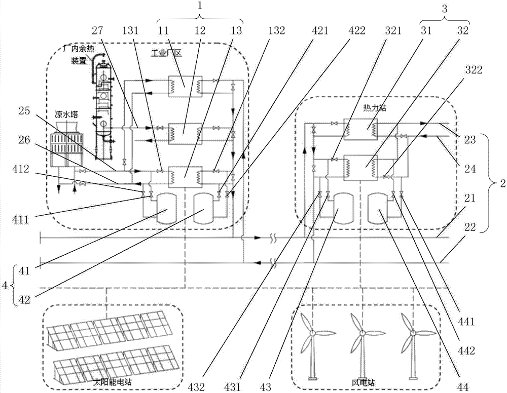
[0081] Such as image 3 As shown, this embodiment provides a centralized heating system for integrated utilization of industrial waste heat, its structure is basically the same as that of Embodiment 2, but the heat storage subsystem 4 of the central heating system in this embodiment also includes a terminal Primary network heat storage tank 43 and terminal secondary network heat storage tank 44 . The tank top interface and tank bottom interface of the terminal primary network heat storage tank 43 are respectively connected with the inlet and outlet of the terminal electric heat pump 32 on the heat-taking side, and the tank top interface and tank bottom interface of the terminal secondary network heat storage tank 44 are respectively connected with the end The outlet of the heat release side of the electric heat pump 32 is connected to the inlet; the inlet of the end electric heat pump 32 is provided with a first end valve 321 and an end second valve 322 respectively on the hea...


PUM


Abstract

The invention relates to a centralized heating system with an industrial waste heat integrated utilization function and a using method thereof. The centralized heating system comprises an industrial waste heat collecting subsystem, a heat transport network and a tail end heat utilization subsystem. The industrial waste heat collecting subsystem comprises a circulating water waste heat collecting device, a low-temperature waste heat material heat exchanger and an in-plant electric heating pump. The heat transport network comprises a primary network water supply pipeline, a primary network water return pipeline, a secondary network water supply pipeline, a secondary network water return pipeline, a circulating water supply pipeline, a circulating water return pipeline and a low-temperature waste heat material pipeline. The tail end heat utilization subsystem comprises a heating network water heat extracting device and a tail end electric heating pump. According to the centralized heating system and the using method thereof, by arranging the combination of the circulating water heat exchanger, the low-temperature waste heat material heat exchanger and the heating pumps on the in-plant heat source side, circulating water waste heat, technological material waste heat and the like can be recycled at a time according to the temperature grade, waste heat which cannot be recycled through direct heat exchange is recycled through the heating pumps, and gradient utilization of the industrial waste heat and optimized utilization of in-plant waste heat resources are achieved.

Description

technical field [0001] The present invention relates to a central heating system and its use method, in particular to a central heating system for integrated utilization of industrial waste heat and its use method. Background technique [0002] Due to the influence of basic chemical principles, the energy utilization efficiency of industrial production is generally not high, and a large amount of waste heat is discharged into the environment in the form of gas, liquid and solid during the production process, resulting in energy waste, and low-grade industrial waste heat accounts for 50% of it. %above. At the same time, my country's heating scale is growing rapidly at an average annual growth rate of 10%, resulting in a shortage of heating sources in northern my country. When heating, the room temperature is generally required to be around 20°C. In theory, any heat source above 20°C can be used for heating. This stable and huge heat demand provides a solution for the applic...

Claims


Application Information

Patent Timeline
Patent Type & Authority Applications(China)
IPC IPC(8): F24D3/02F24D3/18F24D19/10
CPCF24D3/02F24D3/18F24D19/1015F24D19/1039F24D2200/16F24D2200/126Y02B30/12
Inventor 赵玺灵付林孙涛张世钢何正
Owner TSINGHUA UNIV
Why Eureka
Try Eureka