Microfluidic chip based on magnetic fluorescent composite particles
A microfluidic chip and composite particle technology, applied in fluorescence/phosphorescence, laboratory containers, material analysis through optical means, etc., can solve the problems of slow detection speed, inconvenient, complex and expensive equipment, etc., to achieve Eliminate interference, facilitate application, and facilitate on-site rapid detection
- Summary
- Abstract
- Description
- Claims
- Application Information
AI Technical Summary
Problems solved by technology
Method used
Image
Examples
Embodiment 1
[0054] Example 1: Preparation and detection of mAlb (urinary microalbumin, urinary microalbumin) by a planar optical microfluidic chip based on magnetic fluorescent composite nanoparticles.
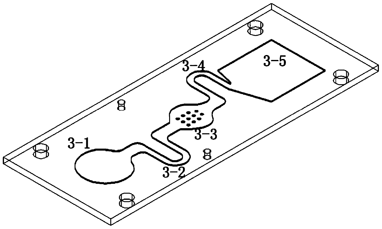
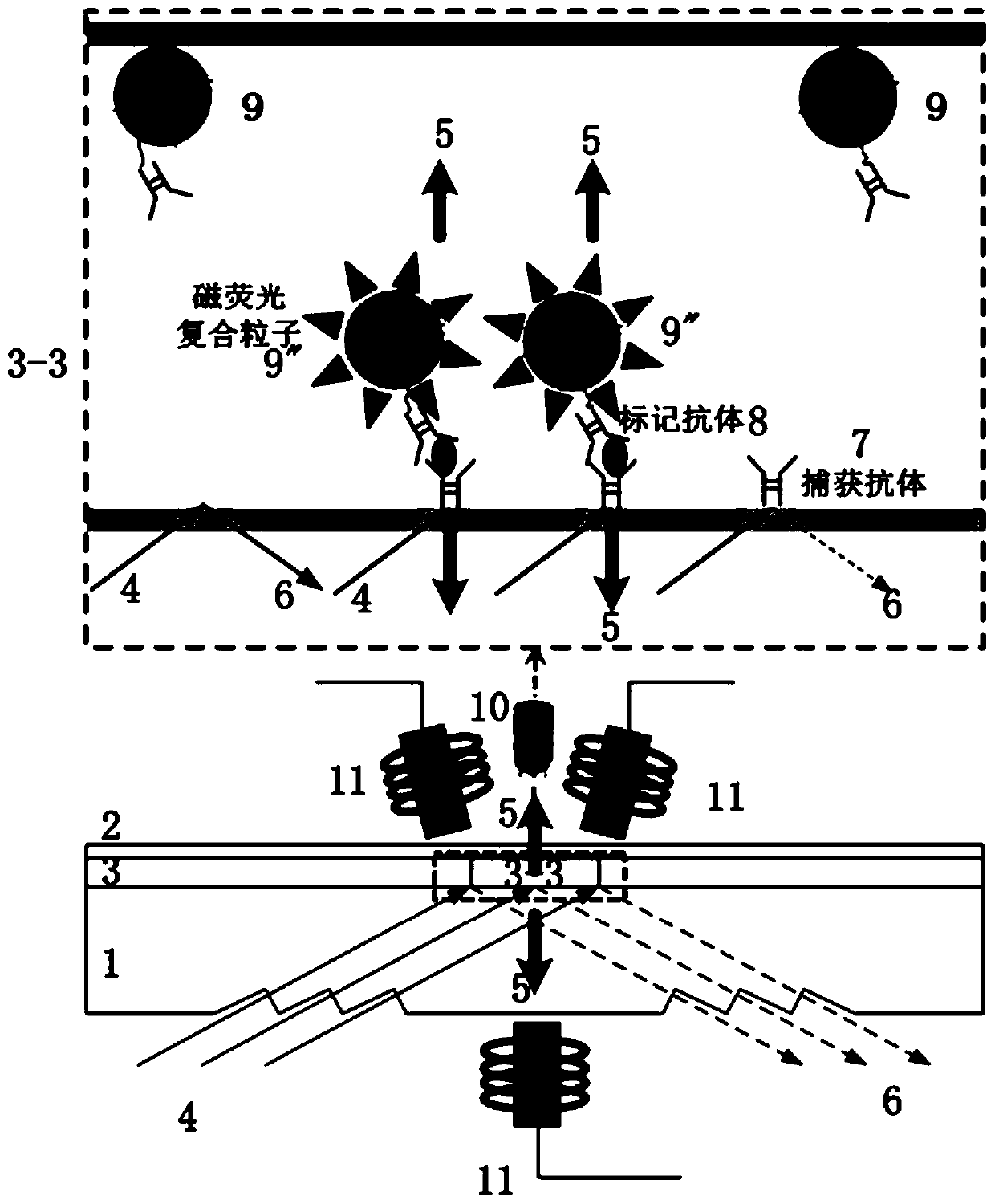
[0055] See figure 1 , 2 , the disposable planar optical microfluidic chip of the present invention is mainly composed of a chip bottom plate 1 , a chip channel layer 3 and a chip top cover plate 2 and the like. Wherein the bottom plate of the chip 1 is designed with a transparent material and has an inward groove at a specific angle in the incident area; The liquid channel 3-4 and the waste liquid storage area 3-5; the chip upper layer cover plate 2 has a hydrophilic film layer. The capture antibody / capture recognition reagent 7 is immobilized on the lower side of the optical detection area 3-3, and the labeled antibody / labeled recognition reagent 8-magnetic fluorescent composite particle 9 is pre-immobilized on the sample injection area 3-1 and the sample injection channel area 3-2. T...
Embodiment 2
[0061] Example 2: see figure 1 , figure 2 , the disposable planar optical microfluidic chip of the present invention is mainly composed of a chip bottom plate 1, a chip channel layer 3 and a chip upper cover plate 2 and the like. Wherein the bottom plate of the chip 1 is designed with a transparent material and has an inward groove at a specific angle in the incident area; The liquid channel 3-4 and the waste liquid storage area 3-5; the chip upper layer cover plate 2 has a hydrophilic film layer. The capture antibody / capture recognition reagent 7 is immobilized on the lower side of the optical detection zone 3-3, and the labeled antibody / labeled recognition reagent 8-magnetic fluorescent composite particle 9 is pre-immobilized on the upper side of the optical detection zone 3-3. The detection device 10 is placed under the optical detection area 3-3, and the electromagnetic module 11 is on the upper and lower sides of the optical detection area 3-3.
[0062] Wherein, the c...
Embodiment 3
[0067] Embodiment 3: see Figure 1-3 , the disposable planar optical microfluidic chip of the present invention is mainly composed of a chip bottom plate 1, a chip channel layer 3 and a chip upper cover plate 2 and the like. This embodiment can use image 3 The side-incidence mode of the planar structure shown has a larger total reflection angle, slightly worse excitation efficiency, and better anti-interference effect. Wherein the bottom plate of the chip 1 adopts a transparent material and has a lateral groove design with a specific angle in the incident area; the chip channel layer 3 includes a sample feeding area 3-1, a sample feeding channel 3-2, an optical detection area 3-3, The waste liquid channel 3-4 and the waste liquid storage area 3-5; the chip top cover plate 2 has a hydrophilic film layer. The capture antibody / capture recognition reagent 7 is immobilized on the lower side of the optical detection zone 3-3, and the labeled antibody / labeled recognition reagent 8...
PUM
| Property | Measurement | Unit |
|---|---|---|
| angle of incidence | aaaaa | aaaaa |
| particle diameter | aaaaa | aaaaa |
| particle diameter | aaaaa | aaaaa |
Abstract
Description
Claims
Application Information
 - R&D
- Intellectual Property
- Life Sciences
- Materials
- Tech Scout
- Unparalleled Data Quality
- Higher Quality Content
- 60% Fewer Hallucinations
Browse by: Latest US Patents, China's latest patents, Technical Efficacy Thesaurus, Application Domain, Technology Topic, Popular Technical Reports.
© 2025 PatSnap. All rights reserved.Legal|Privacy policy|Modern Slavery Act Transparency Statement|Sitemap|About US| Contact US: help@patsnap.com


