CFRP bar connection type anchorage device and construction method

A connecting and anchoring technology, applied in the direction of structural elements, building components, building reinforcements, etc., can solve the problems of CFRP bar connection technology that is rarely researched, improve installation speed and use efficiency, meet dexterity, and increase friction. force effect

Inactive Publication Date: 2017-08-04
JIANGSU UNIV
View PDF5 Cites 2 Cited by
  • Summary
  • Abstract
  • Description
  • Claims
  • Application Information

AI Technical Summary

Problems solved by technology

Due to its excellent characteristics, CFRP bars can be used in structures such as hydraulic engineering, bridge engineering, and prefabricated buildings. At prese...

Method used


Image

  • CFRP bar connection type anchorage device and construction method
  • CFRP bar connection type anchorage device and construction method
  • CFRP bar connection type anchorage device and construction method

Examples


Embodiment 1

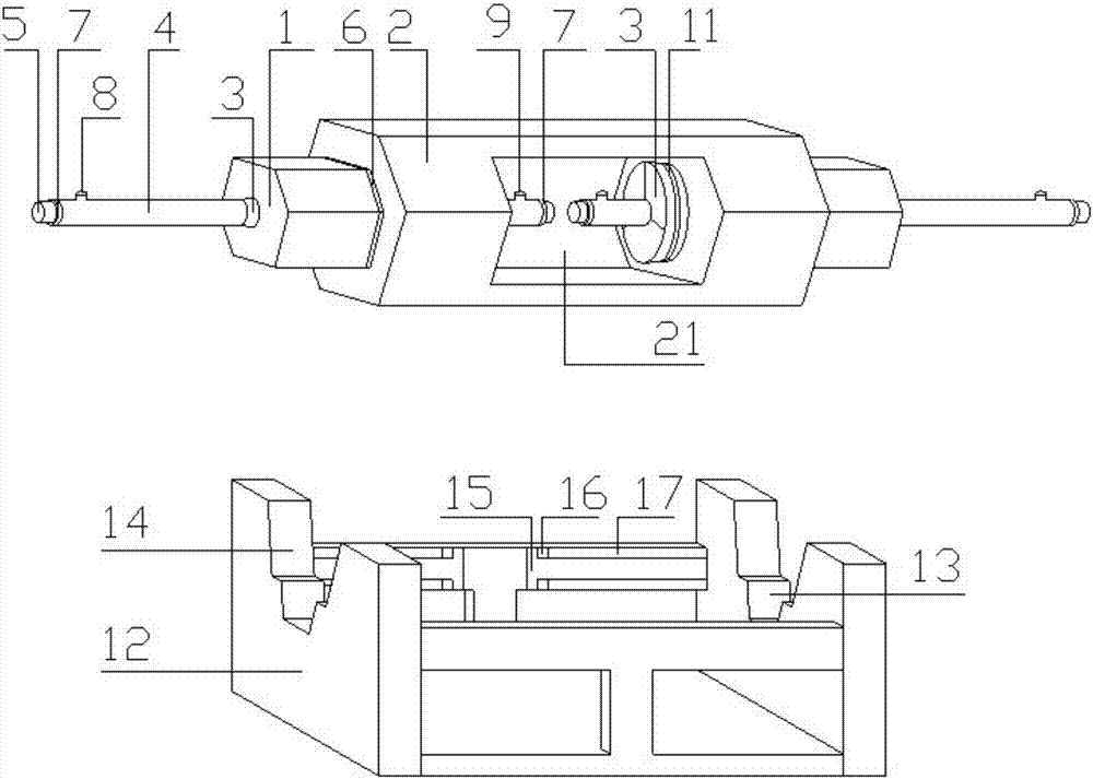
[0065] figure 1 Shown is an embodiment of the CFRP tendon-connected anchor of the present invention. The CFRP tendon-connected anchor includes a metal sleeve 2A, a pair of composite anchors B and a bracket C.

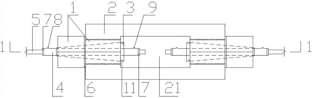
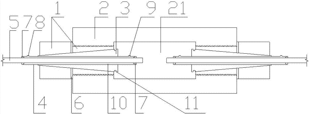
[0066] Such as figure 2 and 3 As shown, the composite anchor includes a regular hexagonal prism anchor ring 1, a clamp 3, a metal cylinder 4 and an end plug 7; the CFRP tendon 5 is placed in the middle of the metal cylinder 4, and a Adhesive glue 10 filling. The two ends of the metal cylinder 4 are provided with a grouting channel 8 and a grouting channel 9 with an inner diameter of 5 mm, and the openings at both ends of the metal cylinder 4 are provided with annular end plugs 7, and the through-hole axis of the metal cylinder 4 is aligned with the CFRP reinforcement The central axes of 5 are consistent, and the CFRP reinforcement 5 and the metal cylinder 4 are provided with fine threads on the outside, the CFRP reinforcement 5 has a thread pitch of 5mm, the metal c...

Embodiment 2

[0085] The difference between this embodiment and Embodiment 1 is that: Figure 10 , 11 , 12, 13, 14 and 15, the support includes two side plates 12, two side portions 17 and a base 18; the upper end of the side plate 12 is provided with a second slot 14, and the second slot The bottom of 14 is provided with a first card slot 13; the upper end of the side part 17 is provided with a third card slot 16, and the third card slot 16 is provided with two first clips 15, and the first clip 15 can be Sliding in the third slot 16; the base 18 is provided with a fourth slot 19, the fourth slot 19 is provided with two second clips 20, the second clip 20 can be in the fourth slot 19 Sliding; the bottom ends of the side plates 12 are respectively symmetrically installed on both ends of the base 18, and are respectively fixedly connected to one end of the second clip 20; the bottoms of the side plates 17 are symmetrically installed on both sides of the base 18, Both ends of the side porti...


PUM


Abstract

The invention provides a CFRP bar connection type anchorage device and a construction method. The CFRP bar connection type anchorage device comprises a metal sleeve, a pair of composite anchorage device bodies and a bracket. Each composite anchorage device body comprises an anchor ring, a fixture, a metal barrel and an end plug. The bracket comprises a side plate, a side part and a base, and a second clamping groove is formed in the upper end of the side plate. A CFRP bar material is placed in the middles of the metal barrels. The position between each metal barrel and the CFRP bar material is filled with adhesive glue. The metal barrels are sleeved with the fixtures, then the fixtures are placed into the anchor rings, and the two ends of the metal sleeve are in threaded connection with the anchor rings correspondingly and then are integrally arranged on the bracket. The CFRP bar connection type anchorage device is easy and convenient to operate and capable of being installed detachably and adapts to site construction, the working condition of the whole anchorage device can be directly observed through a grooving part of the metal sleeve, the slippage amount is small and is within the controllable range, the connection problem of the CFRP bar material is effectively solved, and the anchorage device can bear a certain amount of loads under the premise of not damaging the bar material and can meet related anchoring requirements. Assembling is conducted by matching the bracket of the anchorage device, the installing speed and the using efficiency are improved, and the requirements for flexible, convenient and easy operation and the like on a engineering field are met.

Description

technical field [0001] The patent of the present invention relates to a CFRP tendon connection type anchorage and construction method, specifically a docking device for two CFRP tendons and an on-site construction operation method, which belongs to the field of structural engineering and can be applied to the need to use CFRP tendons Structure. Background technique [0002] Carbon fiber composite reinforced material, referred to as CFRP, has a series of characteristics such as light weight, high strength, and corrosion resistance. It has outstanding advantages in the application of prestressed large-span and super-long-span concrete structures. Compared with traditional high-strength steel, on the one hand, it reduces the weight of the structure and greatly increases the span of the structure; on the other hand, it uses the excellent tensile properties of carbon fiber materials to greatly improve the tensile performance of the structure. However, the shear strength of CFRP ...

Claims


Application Information

Patent Timeline
IPC IPC(8): E04C5/16
CPCE04C5/16E04C5/165
Inventor 刘荣桂张翔宇谢桂华李十泉平舒席宜超
Owner JIANGSU UNIV
Why Eureka
Try Eureka