Turbine blade tail edge turbulence half-crack cooling structure with spherical surface convex block

A turbine blade and trailing edge technology, applied in the direction of blade support components, engine components, machines/engines, etc., can solve problems such as tending to the limit, reduce the maximum temperature and average temperature, avoid high temperature ablation, and improve the gas film Effect of convective heat transfer coefficient and heat transfer area

Inactive Publication Date: 2017-08-04
NORTHWESTERN POLYTECHNICAL UNIV
View PDF7 Cites 10 Cited by
  • Summary
  • Abstract
  • Description
  • Claims
  • Application Information

AI Technical Summary

Problems solved by technology

[0004] In the literature "Experimental Research on the Air Film Cooling Characteristics of Turbine Blade Trailing Slits" ("Journal of Engineering Thermophysics", 2016, No. 37, pp. 1988-1993), the thermochromic liquid crystal transient heat transfer measurement was used to study The effects of two different split rib structures, straight rib and chamfered rib, on the film cooling characteristics of the split ribs in the trailing edge laminate cooling structure are studied, although the conclusion shows that the air film cooling effect of the half-slit trailing edge of the blade is affected by the split ribs. However, with the continuous increase of the gas temperature of the aero-engine, the cooling capacity of the traditional half-slit structure gradually tends to the limit, and the ablation phenomenon of the trailing edge of the high-pressure turbine blade often occurs on the suction side of the trailing edge of the blade, so the development of And the innovative efficient cooling structure of the trailing edge of the turbine blades can further improve the comprehensive cooling effect without increasing the amount of cooling air, which is very necessary and meaningful for the development of advanced high-performance aero-engines

Method used


Image

  • Turbine blade tail edge turbulence half-crack cooling structure with spherical surface convex block
  • Turbine blade tail edge turbulence half-crack cooling structure with spherical surface convex block
  • Turbine blade tail edge turbulence half-crack cooling structure with spherical surface convex block

Examples


Embodiment Construction

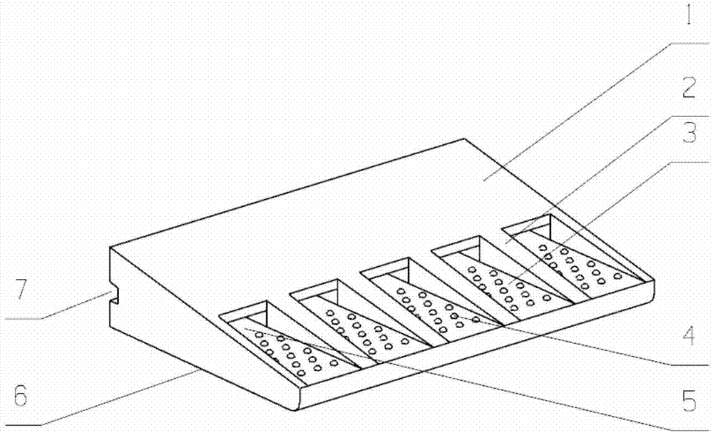
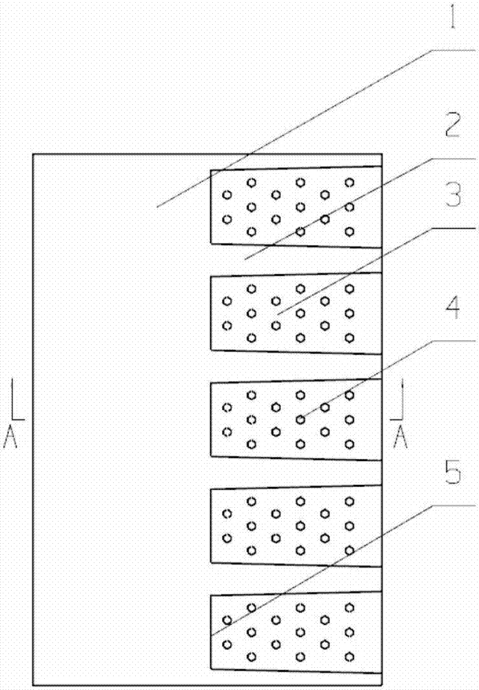
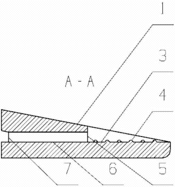
[0023] This embodiment is a turbine blade trailing edge turbulent half-slit cooling structure with spherical bumps.

[0024] refer to Figure 1 to Figure 6 In this embodiment, the turbine blade trailing edge turbulent half split cooling structure with spherical projections is applied to the turbine blade of an aero-engine. Suction surface 6, blade trailing edge pressure surface 1, trailing edge half-slit wall surface 3, partition rib 2, spherical bump 4, cold flow outlet 5, and cold flow inlet 7; among them, the part cut off from the blade trailing edge pressure surface 1 On the wall surface, the wall surface on the side where the suction surface 6 of the blade trailing edge is retained and the spaced partition ribs 2 form a plurality of half-slit structures; the ratio of the thickness t of the lip plate of the half-slit structure to the height s of the cold air outflow slot is 0.2 to 1.5, The inclination angle of the half-slit is 0-15°, and the cooling air flow is sprayed fr...


PUM


Abstract

The invention discloses a turbine blade trailing edge turbulent half-split cooling structure with spherical bumps. The spherical bump structure is applied to the wall surface of the half-split slot. The structure improves the convective heat transfer coefficient and heat transfer area of ​​the air film, and enhances the convective heat transfer intensity of the half-split air film cooling, thereby improving the comprehensive cooling effect of the blade trailing edge. Turbine blade trailing edge turbulent half-split cooling structure with spherical bumps is to cut off part of the wall on the pressure surface of the trailing edge of the blade, and retain the wall on the suction side of the trailing edge and the spaced separation ribs to form multiple half-split slits Structure; it is characterized in that the cooling airflow is sprayed from the cold flow outlet and covers the half-split slit wall surface to form a cooling air film, the structure is simple, and the maximum temperature and average temperature of the suction surface are effectively reduced to avoid high temperature ablation of the suction surface of the turbine blade ; The spherical bump structure is arranged on the wall surface of the half-split slit, which has good heat transfer characteristics and processing practicability.

Description

technical field [0001] The invention belongs to the technical field of gas turbine blade cooling, and in particular relates to a turbine blade trailing edge turbulence half-slit cooling structure with spherical bumps. Background technique [0002] Increasing the turbine inlet temperature is an effective way to improve the thrust and efficiency of gas turbines, but the increase in turbine inlet temperature will cause the turbine blades to bear a greater heat load, and excessive temperature and thermal stress may cause the turbine blades to fail to work properly. The inlet temperature of modern gas turbine design has far exceeded the temperature limit of the materials used, so complex cooling technology must be used to ensure the normal operation of the turbine under high temperature conditions. The trailing edge of the turbine blade is often a high-temperature part, and is also the most vulnerable to heat corrosion and damage. The main reason is that the gas side flow at the ...

Claims


Application Information

Patent Timeline
Patent Type & Authority Applications(China)
IPC IPC(8): F01D5/18
CPCF01D5/186F05D2220/32F05D2240/30F05D2260/202F05D2260/2214
Inventor 刘存良叶林刘海涌郭奇灵高超
Owner NORTHWESTERN POLYTECHNICAL UNIV
Why Eureka
Try Eureka