A coal-fired boiler sncr and scr combined denitrification system and method

A technology for coal-fired boilers and SCR reactors, applied in chemical instruments and methods, separation methods, lighting and heating equipment, etc., can solve problems such as uneven distribution, inability to mix evenly, corrosion, etc., and achieve uniform distribution of ammonia-nitrogen molar ratio, Efficient and low-cost removal and improved distribution uniformity

Active Publication Date: 2017-12-01
CHINA HUANENG GRP CO LTD +1
View PDF1 Cites 0 Cited by
  • Summary
  • Abstract
  • Description
  • Claims
  • Application Information

AI Technical Summary

Problems solved by technology

[0009] In the existing SNCR+SCR combined denitrification technology, such as the invention patent 201010130558.3 ​​method for realizing combined SNCR and SCR denitrification of coal-fired boilers, a single-nozzle spray gun (that is, a short wall-type spray gun) is used to spray urea solution into the furnace. The distance into the furnace is limited, and the NH produced by pyrolysis cannot be well 3 and HNCO are evenly mixed with NOx in the flue gas. Although a steam turbulence device is installed at the flue turning chamber, this steam turbulence device can only improve the NH to a certain extent. 3 and the mixing uniformity of HNCO and NOx in the flue gas
NH produced by pyrolysis of urea cannot be made due to existing technology 3 and HNCO are evenly mixed with NOx in flue gas, so the denitrification efficiency of SCR is limited to a certain extent
If the molar ratio of ammonia nitrogen entering the SCR reactor is unevenly distributed on the cross section, it is easy to cause a large amount of ammonia to escape from the SCR reactor and enter the air preheater
In the air preheater, ammonia in the flue gas meets SO 3 will generate NH 4 HSO 4 , NH 4 HSO 4 Adhering to the heating surface of the cold end of the air preheater, adhering to the dust in the flue gas, it is easy to cause the air preheater to be blocked and cause corrosion

Method used


Image

  • A coal-fired boiler sncr and scr combined denitrification system and method

Examples


Embodiment Construction

[0030] The present invention will be further described in detail below in conjunction with specific embodiments, which are explanations of the present invention rather than limitations.

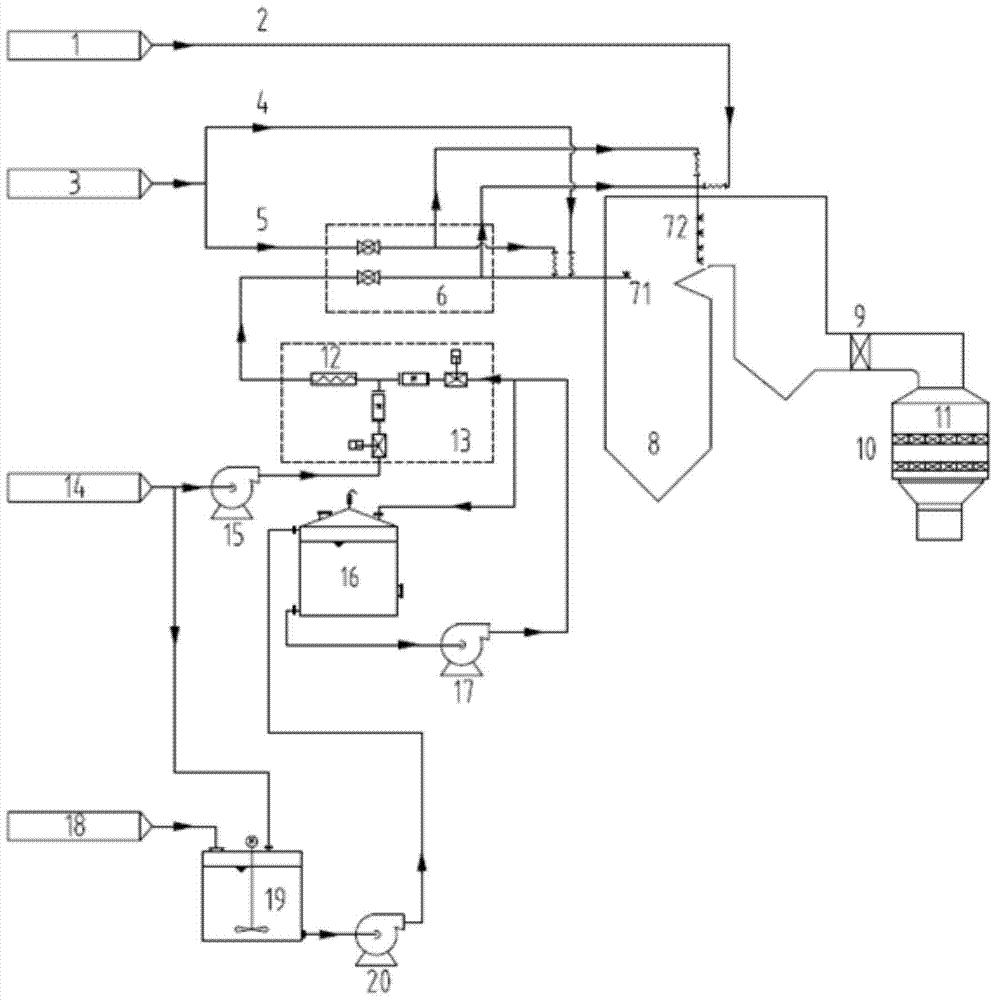
[0031] The present invention is a coal-fired boiler SNCR and SCR combined denitrification method, through the short spray gun 71 and the multi-hole long spray gun 72 installed in the furnace chamber when the boiler SNCR reacts, and the flue gas mixer 9 and the SCR smoke installed in the tail flue of the boiler. Road reactor, no need to add SCR reductant injection device, overcome the low denitrification efficiency caused by uneven mixing of reductant and NOx in the existing process, equipment blockage and corrosion caused by large ammonia escape, and realize the overall comparison of SNCR and SCR systems High denitrification efficiency. At the same time, the SCR reactor can be modified by using the tail flue of the boiler, which saves the floor area required by the SCR project and reduces the...


PUM


Abstract

The present invention relates to a coal-fired boiler SNCR and SCR combined denitrification system, which includes a boiler SNCR reaction system and an SCR reactor; the boiler SNCR reaction system includes a boiler, a urea solution distribution module and a metering module, and a system connected by the urea solution distribution module and the metering module Urea injection system and urea supply system; the urea injection system includes short spray guns arranged in multiple layers within the range of 25m to 40m above the boiler furnace combustion zone, and multi-layer long porous spray guns at the position of the boiler deflection angle. At least one porous long spray gun is arranged vertically into the boiler and extends through its cross-section; the SCR reactor is connected to the tail of the boiler through the flue gas mixer; inside the SCR reactor, it is located in the economizer and the air preheater A multi-layer honeycomb catalyst is arranged in the space between them. The method makes the molar ratio distribution of the ammonia nitrogen entering the inlet section of the SCR catalyst uniform, and improves the denitrification efficiency of the SCR reactor.

Description

technical field [0001] The invention relates to a denitrification system of a power plant, in particular to a coal-fired boiler SNCR and SCR combined denitrification system and method. Background technique [0002] In my country's energy structure, coal occupies a major position. A significant portion of coal consumption is used for electricity production. Nitrogen oxide (NOx) produced by coal-fired power generation is one of the main pollutants causing air pollution. [0003] The reduction of NOx emissions from coal-fired power plants can be achieved through technologies such as low NOx combustion, selective non-catalytic reduction (SNCR) and selective catalytic reduction (SCR). Low NOx combustion is based on the formation mechanism of NOx in the boiler, using technologies such as low NOx combustion method, low NOx burner and low NOx furnace to reduce the production of nitrogen oxides. Selective non-catalytic reduction denitrification technology is to spray the reducing ...

Claims


Application Information

Patent Timeline
Patent Type & Authority Patents(China)
IPC IPC(8): B01D53/75B01D53/56F23J15/04
Inventor 高宁董陈张向宇张波向小凤陆续徐宏杰
Owner CHINA HUANENG GRP CO LTD
Why Eureka
Try Eureka