Active control device of supersonic blunt trailing edge mixed layer

An active control, supersonic technology, applied in the field of supersonic speed, it can solve problems such as control failure and melting of the vibration plate, and achieve the effect of avoiding easy melting and simple mechanical structure.

Active Publication Date: 2017-08-04
NAT UNIV OF DEFENSE TECH
View PDF5 Cites 10 Cited by
  • Summary
  • Abstract
  • Description
  • Claims
  • Application Information

AI Technical Summary

Problems solved by technology

In actual engineering practice, the high-temperature gas in the combustion chamber of the combined engine will easily melt the vibrating plate, resulting in control failure

Method used


Image

  • Active control device of supersonic blunt trailing edge mixed layer
  • Active control device of supersonic blunt trailing edge mixed layer
  • Active control device of supersonic blunt trailing edge mixed layer

Examples


Embodiment Construction

[0031] The accompanying drawings constituting a part of this application are used to provide further understanding of the present invention, and the schematic embodiments and descriptions of the present invention are used to explain the present invention, and do not constitute an improper limitation of the present invention.

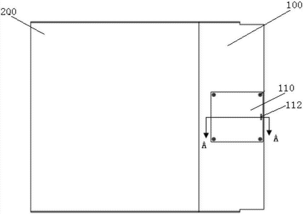
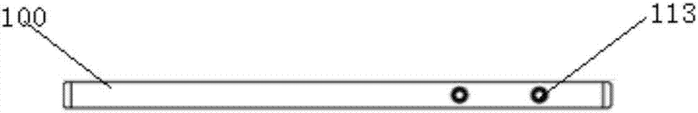
[0032] see Figure 2~4 , the active control device for the supersonic obtuse trailing edge mixed layer provided by the present invention is arranged on the trailing edge of the partition away from the end of the supersonic incoming flow 300 .

[0033] The separator may be a first separator part 100 and a second separator part 110 connected to each other at one end. The splicing here can be plug splicing or glue splicing. In one embodiment, the first partition 100 and the second partition 110 are connected by fixing screws 113 , and the fixing screws 113 pass through the first partition 100 and then connect with the second partition 110 .

[0034] see ...


PUM


Abstract

The invention provides an active control device of a supersonic blunt trailing edge mixed layer. By arranging a jet flow active control structure in the trailing edge of a partition plate, active control and passive control are combined, the problem that as for active control, vibrating plates are prone to melting is avoided, and various control modes can be freely selected. The active control device achieves the effects that active control and passive control are combined and complement each other.

Description

technical field [0001] The invention relates to the field of supersonic technology, in particular to an active control device for a supersonic obtuse trailing edge mixed layer. Background technique [0002] Ejection refers to the supersonic mixing of rocket gas and incoming air during rocket launch. This process is a key process of Rocket Based Combined Cycle (RBCC). For RBCC, the free incoming flow passes through a series of The intake port is in contact with the nozzle gas at the nozzle trailing edge. When the mixture of the two reaches the molecular level, a chemical reaction can occur, so as to achieve the purpose of increasing the specific impulse of the engine by using the oxygen in the air. However, due to the high flow velocity, the air can only stay in the combustion chamber for <1-3ms. The injection efficiency depends on whether the gas can be mixed with the air quickly and efficiently, and at the same time determines the performance of the entire propulsion sys...

Claims


Application Information

Patent Timeline
Patent Type & Authority Applications(China)
IPC IPC(8): F02K9/82
CPCF02K9/82
Inventor 杨瑞王振国吴继平罗振兵邓雄
Owner NAT UNIV OF DEFENSE TECH
Why Eureka
Try Eureka