Whispering gallery mode optical resonant cavity temperature sensing system

A technology of optical resonant cavity and whispering gallery mode, applied in the field of optics, can solve problems such as inability to meet high-precision measurement requirements, and achieve the effects of small size, high sensitivity, and easy integration

Active Publication Date: 2017-08-04
浙江知多多网络科技有限公司
View PDF10 Cites 14 Cited by
  • Summary
  • Abstract
  • Description
  • Claims
  • Application Information

AI Technical Summary

Problems solved by technology

With the development of temperature sensing application requirements, in many cases, the exis

Method used


Image

  • Whispering gallery mode optical resonant cavity temperature sensing system

Examples


specific Embodiment approach 1

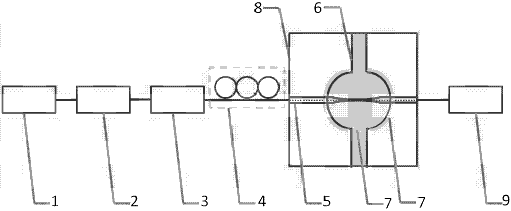
[0013] Specific implementation mode one: as figure 1 As shown, the WGM optical resonant cavity temperature sensing system described in this embodiment includes a broadband light source 1, an isolator 2, an attenuator 3, a polarization controller 4, an optical fiber taper 5, and a WGM resonant cavity structure (with a temperature-sensitive medium 7 inside and outside The bubble chamber 6), the box 8 for fixing the resonator and the fiber cone, and the spectrometer 9. The transmitting end of the broadband light source 1 is connected to the input end of the isolator 2, the output end of the isolator 2 is connected to the input end of the attenuator 3, and the optical fiber between the output end of the attenuator 3 and the input end of the fiber cone 5 is provided with a polarization controller4. The light field in the fiber taper 5 enters the resonant cavity through evanescent wave coupling, and the light field in the cavity can also be coupled to the receiving end of the spect...

specific Embodiment approach 2

[0014] Specific implementation mode two: combination figure 1 This embodiment is described. This embodiment is a further limitation of the WGM optical resonant cavity temperature sensing system described in Embodiment 1. The temperature-sensitive medium 7 in the bubble cavity 6 does not need to be completely filled, as long as the light in the cavity is ensured You can feel the change of its refractive index during circulation. The temperature-sensitive medium coated outside the bubble chamber 6 only needs to cover the optical field sensing path. And the temperature-sensitive medium inside and outside the cavity must ensure that the optical field can be transmitted in the resonant cavity.

specific Embodiment approach 3

[0015] Specific implementation mode three: combination figure 1 This embodiment is described. This embodiment is a further limitation of the WGM optical resonant cavity temperature sensing system described in Embodiment 1. First, the resonant cavity is fixed in the box 8, and the light is coupled into the resonant cavity by the light cone 5. Drop UV-curable glue at the contact position between the fiber cone and the box 8, continue to adjust the position of the fiber cone 5 to the best coupling state, and use ultraviolet light to cure the glue, and then fix the position of the fiber cone.


PUM


Abstract

The present invention discloses a whispering gallery mode optical resonant cavity temperature sensing system. The transmitting end of the broadband light source of the system is connected with the input end of an isolator. The output end of the isolator is connected with the input end of an attenuator. An optical fiber between the output end of the attenuator and the input end of an optical fiber taper is provided with a polarization controller. A light field in the optical fiber taper enters a resonant cavity through the evanescent wave coupling manner. The light field in the cavity is in coupled output to the receiving end of a spectrograph through optical fibers. In the sensing system, the broadband light source, the isolator, the attenuator, the polarization controller, the optical fiber taper and the spectrometer are connected through optical fibers. According to the whispering gallery mode optical resonant cavity temperature sensing system, a temperature sensitive medium is introduced inside and outside a gas bubble cavity, so that the temperature sensing accuracy of the resonant cavity is improved. The system can be applied to the high-precision temperature measurement.

Description

technical field [0001] The invention relates to a Whispering gallery mode (Whispering gallery mode, WGM) optical resonant cavity temperature sensing system, which belongs to the field of optics. Background technique [0002] As one of the seven basic physical quantities of international units, temperature plays an important role in physics. Temperature measurement is very important to national economy, national defense construction and scientific research. With the development of temperature sensing application requirements, in many cases, the existing temperature sensing system can no longer meet the high-precision measurement requirements. The optical resonant cavity, which is easy to integrate with the optical fiber system, small in size, and capable of remote monitoring, has high measurement accuracy and has its own unique advantages in temperature measurement. We design a high-precision temperature sensing system using WGM optical resonator, which can accurately measur...

Claims


Application Information

Patent Timeline
IPC IPC(8): G01K11/32
CPCG01K11/32
Inventor 于长秋钱正洪白茹朱华辰
Owner 浙江知多多网络科技有限公司
Why Eureka
Try Eureka