Molding method of tubular composite material part

A composite material and molding method technology, applied in the field of material processing and molding, can solve problems such as reducing production efficiency, increasing labor intensity, manpower, physics, and energy waste, saving mold and energy costs, improving price competitiveness, and improving Effects of working conditions

Inactive Publication Date: 2017-08-08
TAISHAN SPORTS IND GRP +1
View PDF6 Cites 6 Cited by
  • Summary
  • Abstract
  • Description
  • Claims
  • Application Information

AI Technical Summary

Problems solved by technology

There are three problems in this process: First, the upper and lower planes of the mold are in direct contact with the heating or cooling furnace to complete the heat transfer. There is a temperature difference inside the mold from the upper and lower planes to the middle, which causes the product to The problem of uneven temperature, which in turn causes uneven curing of epoxy resin-based composite materials, resulting in internal stress of the product
In industrial production, workers need to frequently open and close molds and move molds. The heavy rigid molds cause heavy physical loads for workers, increase the labor intensity of workers, and reduce production efficiency.
Rigid molds are costly to manufacture, maintain and use, and heavy molds have the potential to injure workers
Third, heating and curing light-weight carbon fiber composite materials requires very little heat, but the method of heating outside the mold must first heat the heavy rigid mold to the required temperature before the product can finally be heated to the required temperature. required temperature
To sum up, the current molding method has problems such as internal stress caused by uneven heating of the product, heavy mold workers, heavy labor, and insufficient release of factory production capacity, resulting in serious waste of manpower, physics, and energy.
These problems seriously restrict the reduction of the production cost of composite products represented by carbon fiber composite bicycles, making it difficult for consumers to bear relatively high purchase costs, which in turn affects the role of carbon fiber bicycles in energy conservation, environmental protection, green travel, and healthy travel.

Method used


Image

  • Molding method of tubular composite material part
  • Molding method of tubular composite material part

Examples


Embodiment Construction

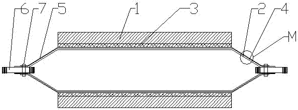
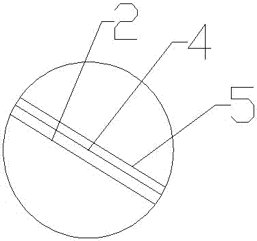
[0028] Accompanying drawing is the specific embodiment of the present invention. Such as figure 1 , figure 2 As shown, the method for forming a tubular composite material part includes the following steps:

[0029] 1) The tubular rigid mold 1 inlaid or bonded with high-temperature-resistant engineering plastics is machined and slotted according to the shape of the bicycle frame to make a special molding mold 3 for internal heating. The special molding mold 3 is also a heat insulation layer and high-temperature-resistant engineering plastics It can be made of polytetrafluoroethylene material; the tubular rigid mold 1 is a split mold, which is surrounded by two arc-shaped plates with a semicircular cross-section, and has high rigidity and high strength to facilitate the insertion and removal of materials ;

[0030] 2) According to the shape of the bicycle, subtract the air bag 2 and the thickness required for the design to obtain the size of the mandrel for covering;

[003...


PUM


Abstract

The invention relates to the field of material processing and molding, and particularly discloses a molding method for tubular composite material parts. It includes the following steps: 1) Install special molding tools in the tubular rigid mold; 2) Calculate the size of the core mold; 3) Wrap the air bag, nylon film and prepreg on the core mold in sequence; 4) Remove the core mold and install 5) Place the fluid interface at both ends of the air bag and tie it tightly with high-temperature tape; 6) Pass high-temperature gas or liquid into the air bag. The invention avoids internal stress caused by uneven heating of required products, abandons expensive and heavy rigid molds, improves the working conditions of workers, reduces energy consumption by more than 90%, saves mold and energy costs, and improves product price competition Advantage.

Description

[0001] (1) Technical field [0002] The invention relates to the field of material processing and molding, in particular to a method for molding tubular composite material parts. [0003] (2) Background technology [0004] In recent years, the concept of low-carbon environmental protection and physical fitness has become more and more popular, and green, environmentally friendly and healthy bicycle travel is deeply loved by the general public. Middle and high-end carbon fiber composite bicycles are becoming a fashion. However, most of the current carbon fiber bicycle frames are covered with carbon fiber-epoxy resin prepreg, heated and pressurized. During the molding process, the coated prepreg is put into a preheated special rigid mold, and then the mold is placed on the high-temperature molding furnace platform. After heating and pressurizing for a period of time, the mold is placed on the cooling platform to cool down. The product can be taken out. There are three problems...

Claims


Application Information

Patent Timeline
Patent Type & Authority Applications(China)
IPC IPC(8): B29C70/44B29C70/54B29C35/04B29L31/30
CPCB29C70/44B29C35/04B29C70/54B29L2031/3091
Inventor 李胜业龙国荣王春青邓龙洵张瑞林徐培明
Owner TAISHAN SPORTS IND GRP
Why Eureka
Try Eureka