Can movable tooth frame two-phrase swinging-plate type internal combustion engine

A technology of movable racks and internal combustion engines, which is applied in the direction of mechanical equipment, machines/engines, belts/chains/gears, etc. It can solve the problems of shortened life of internal combustion engines, large unbalanced centrifugal force, and large volume, and achieves compact structure and radial dimensions. Reduced effect

Inactive Publication Date: 2017-08-08
SICHUAN UNIV
View PDF6 Cites 2 Cited by
  • Summary
  • Abstract
  • Description
  • Claims
  • Application Information

AI Technical Summary

Problems solved by technology

Since this kind of internal combustion engine drives the crankshaft to rotate by the linear motion of the piston and the plane motion of the connecting rod, there is a large friction between the motion pairs, resulting in low transmission efficiency of the internal combustion engine.
The crankshaft connecting rod type internal combustion engine also has the following major defects: large volume; large unbalanced centrifugal force on the connecting rod and crankshaft; large impact and large vibration; and thus cause large mechanical wear and shorten the life of the internal combustion engine; complex structure, Processing, manufacturing, assembly, etc. are more difficult
[0003] In addition, usually the internal combustion engine and the speed change device are two independent machines, and the internal combustion engine needs to be installed with a transmission for subsequent speed change, resulting in a bulky

Method used


Image

  • Can movable tooth frame two-phrase swinging-plate type internal combustion engine
  • Can movable tooth frame two-phrase swinging-plate type internal combustion engine
  • Can movable tooth frame two-phrase swinging-plate type internal combustion engine

Examples


Embodiment Construction

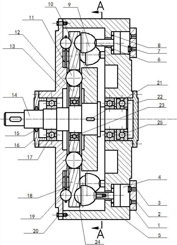
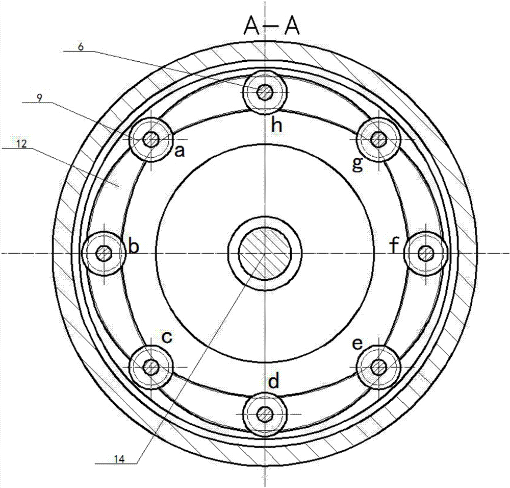
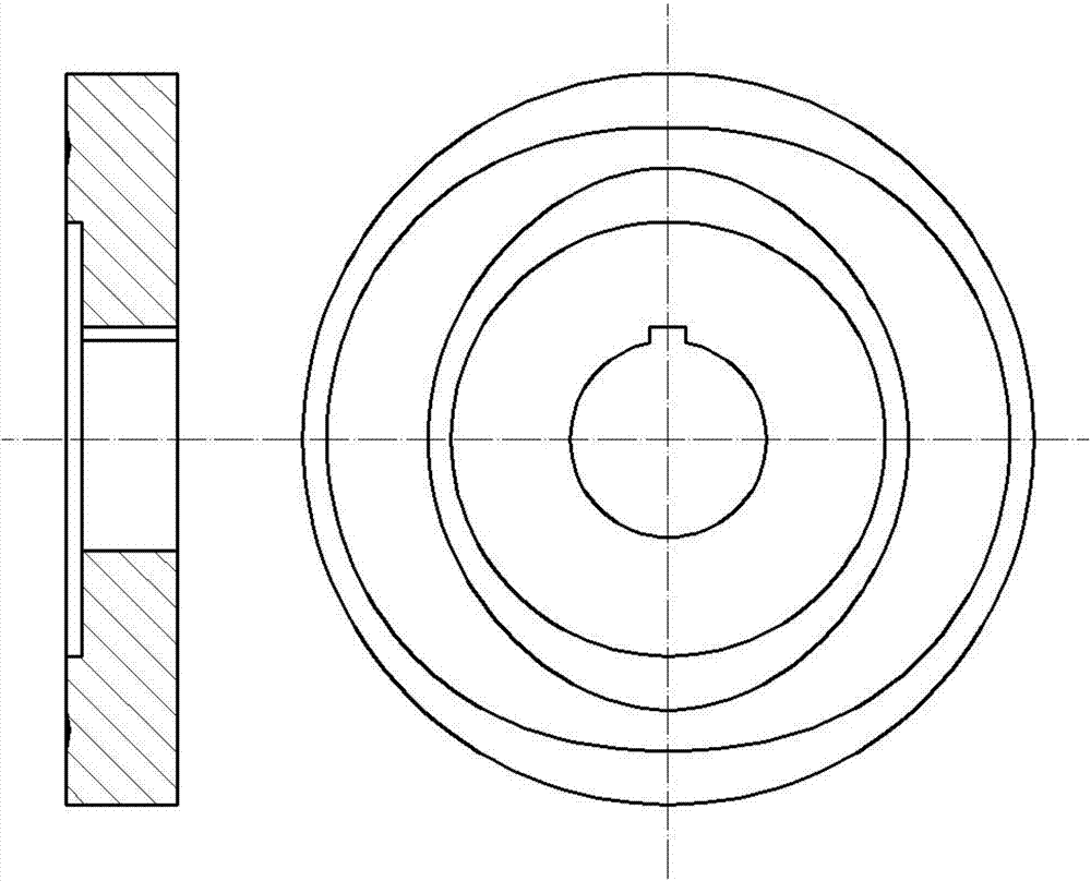
[0041] Figure 1 to Figure 12The two-phase oscillating plate internal combustion engine shown in the cam movable rack is mainly composed of a cylinder head (1), an intake valve (2), an exhaust valve (3), a cylinder (4), a cylinder block (5), a push rod (6 ), piston (7), spring (8), universal ball assembly (9), two-phase wobble plate shock (10), steel ball movable tooth (11), cam movable tooth rack (12), left cover end Gear (13), output shaft (14), sealing ring (15), output end bearing cover (16), deep groove ball bearing (17), cage (18), supporting steel ball (19), screw (20) , key (21), cylinder end bearing cover (22), deep groove ball bearing (23), universal steel ball (24), thrust ball bearing (25), it is characterized in that: the swing plate mechanism with cam movable gear rack Replacing the crankshaft linkage mechanism in the existing crankshaft linkage type internal combustion engine, eight cylinders (4) are set on the right side of the cam movable gear frame (12), and...


PUM


Abstract

The invention provides a can movable tooth frame two-phrase swinging-plate type internal combustion engine, relates to the field of fuel gas power and belongs to a multi-cylinder internal combustion engine. According to the novel internal combustion engine provided by the invention, pistons act on a can movable tooth frame through push rods and universal ball assemblies, and power is transmitted to an output shaft in key linkage with a two-phrase swinging-plate wave generator through a slot-type two-phrase swinging-plate movable tooth transmission mechanism and is output. The can movable tooth frame integrates the internal combustion engine and a can movable tooth frame swinging-plate mechanism, and the internal combustion engine does not need to be additionally equipped with a speed increaser. A crankshaft connecting rod system in a crankshaft connecting rod type internal combustion engine is omitted, no eccentric mass exists in the internal combustion engine, all types of internal force are balanced automatically, steel ball movable teeth and left-cover-end gears are in multi-tooth engagement, the can movable tooth frame and the two-phrase swinging-plate wave generator are also in multi-tooth engagement, and all air cylinders are axially arranged. The internal combustion engine is simple and compact in structure, small in size, large in overlapped degree and high in bearing capacity and can be widely applied to the fields in need of a high rotation speed and large power, such as small generators and helicopter engines.

Description

technical field [0001] The invention relates to the field of gas power, and more specifically relates to a two-phase swing plate type internal combustion engine with a cam movable rack. Background technique [0002] The most commonly used internal combustion engine at present is a reciprocating four-stroke crankshaft connecting rod type internal combustion engine. The transmission structure of this internal combustion engine all adopts a crankshaft connecting rod mechanism, and the crankshaft is driven by the connecting rod, thereby converting the linear motion of the piston into the rotary motion of the crankshaft. Because this internal combustion engine drives the crankshaft to rotate by the linear motion of the piston and the planar motion of the connecting rod, there is a large friction between the kinematic pairs, resulting in low transmission efficiency of the internal combustion engine. The crankshaft connecting rod type internal combustion engine also has the followi...

Claims


Application Information

Patent Timeline
Patent Type & Authority Applications(China)
IPC IPC(8): F02B75/32F02B75/18F02B75/02F16H49/00
CPCF02B75/02F02B75/18F02B75/32F02B2075/027F02B2075/1832F16H49/001
Inventor 梁尚明屈九洲晏晓飞
Owner SICHUAN UNIV
Why Eureka
Try Eureka