Substrate mounting table and substrate processing device

A technology for a substrate processing device and a mounting table, which is applied in the directions of discharge tubes, electrical components, circuits, etc., can solve the problems of difficulty in adopting these technologies, insufficient heat transfer, uneven heat transfer, etc., and achieves good and uniform heat transfer. Good maintainability , the effect of uniform temperature

Active Publication Date: 2020-03-31
TOKYO ELECTRON LTD
View PDF9 Cites 0 Cited by
  • Summary
  • Abstract
  • Description
  • Claims
  • Application Information

AI Technical Summary

Problems solved by technology

However, if a gel-like polymer is used, it is difficult to restore once deformed, so it cannot be used repeatedly, and the maintainability is poor
In addition, if a carbon sheet is used, the minute gap cannot be followed, so the minute gap cannot be fully filled, the heat transfer becomes insufficient and uneven, and it is difficult to eliminate the unevenness of the temperature on the surface of the substrate mounting table.
In addition, in the case of carbon sheets, there is also the problem of dust from the truncated surface
Therefore, it is difficult to adopt these techniques as techniques for solving the above-mentioned problems

Method used


Image

  • Substrate mounting table and substrate processing device
  • Substrate mounting table and substrate processing device
  • Substrate mounting table and substrate processing device

Examples


no. 1 Embodiment approach

[0058] First, the first embodiment will be described.

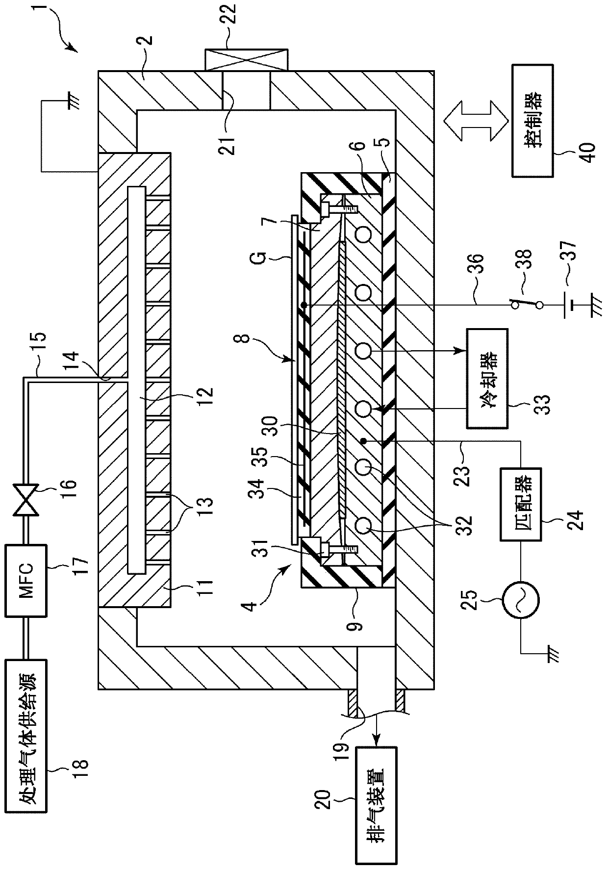
[0059] figure 1 It is a sectional view showing a plasma etching apparatus as an example of a substrate processing apparatus using the substrate mounting table according to the first embodiment of the present invention.

[0060] Such as figure 1 As shown, this plasma etching apparatus 1 is configured as a capacitively coupled parallel plate plasma etching apparatus for etching a rectangular glass substrate (hereinafter abbreviated as “substrate”) G for FPD. Examples of the FPD include a liquid crystal display (LCD), an electroluminescence (EL) display, a plasma display panel (PDP), and the like.

[0061] The plasma etching apparatus 1 includes a chamber 2 serving as a processing container that accommodates a substrate G that is a substrate to be processed. The chamber 2 is formed of, for example, aluminum whose surface is anodized (anodized), and is formed in a rectangular cylinder shape corresponding to the shape of the ...

no. 2 Embodiment approach

[0102] Next, a second embodiment will be described.

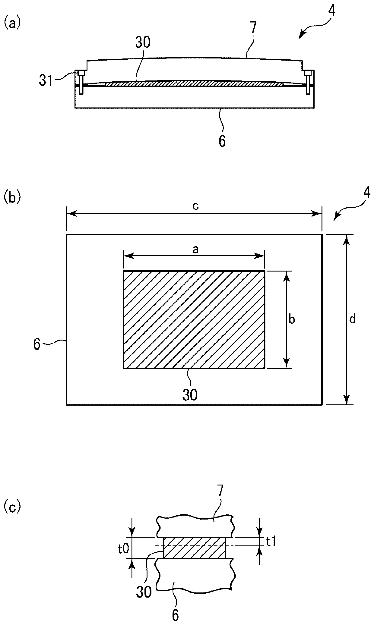
[0103] Figure 6 It is a cross-sectional view showing a substrate mounting table according to a second embodiment of the present invention. In the present embodiment, it is an example of a substrate mounting table for mounting a large substrate. Between the first member 6 and the second member 7, as fastening members, in addition to the outer peripheral screw 31, there is an inner part from the first member. The inner screw 41 is inserted into the back side of the member 6 , and the first member 6 and the second member 7 are fastened by the outer peripheral screw 31 and the inner screw 41 .

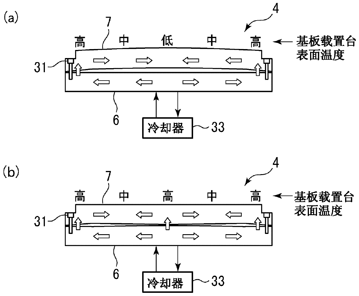
[0104] At this time, when the first member 6 and the second member 7 are directly fastened by the outer peripheral screw 31 and the inner screw 41, a slight gap may be generated in parts other than the fastened part. For example, if Figure 7 As shown in (a), a slight gap is generated between the portion between the outer peripheral s...


PUM


Abstract

To provide a substrate mounting table capable of ensuring good and uniform heat transmission from a first member to a second member, without causing degradation of the maintainability or increase in the device cost, even if there is a small gap between the first member and the second member. A substrate mounting table for mounting a substrate in a substrate processing apparatus for processing a processed substrate in a processing container, has a metal first member becoming the base, a metal second member provided on the first member, a substrate mounting part provided on the surface of the second member and mounting the substrate, temperature control means provided in the first member, an elastic sheet interposed between the first member and second member, and composed of an elastomer of organic material, and a screw for fastening at least the outer boundary of the first member 6 and second member while interposing the elastic sheet. When the first member and second member are fastened, the elastic sheet fills the small gap therebetween.

Description

technical field [0001] The present invention relates to a substrate mounting table for mounting a substrate and a substrate processing apparatus using the same. Background technique [0002] In the manufacturing process of a flat panel display (FPD), the processed substrate is subjected to etching, sputtering, CVD (chemical vapor deposition) and other treatments. [0003] As a substrate processing apparatus for performing such a process, for example, a substrate processing apparatus is known in which a pair of parallel flat electrodes (upper and lower electrodes) are arranged in a processing container and placed on a metal substrate mounting table functioning as a lower electrode. Place the substrate to be processed, and keep the chamber in a vacuum state, apply high-frequency power to at least one of the electrodes to form a high-frequency electric field between the electrodes, and use the high-frequency electric field to form plasma of the processing gas to treat the subst...

Claims


Application Information

Patent Timeline
Patent Type & Authority Patents(China)
IPC IPC(8): H01L21/67H01L21/683H01J37/32
CPCH01J37/32724H01J2237/2001H01L21/67103H01L21/6831H01L21/02315H01L21/3065H01L21/32136H01L21/324H01L21/67098H01L21/67248H01L21/6835
Inventor 佐佐木芳彦南雅人
Owner TOKYO ELECTRON LTD
Why Eureka
Try Eureka