Stirring mechanism of glass fiber cloth gluing device

A technology of glass fiber cloth and stirring mechanism, which is applied in the directions of mixer accessories, mixers with rotary stirring devices, and devices for coating liquid on the surface, etc. Low problems, to achieve the effect of improving the quality of gluing, the best impregnation effect, and high work efficiency

Active Publication Date: 2019-06-28
浙江凯澳新材料有限公司
View PDF7 Cites 0 Cited by
  • Summary
  • Abstract
  • Description
  • Claims
  • Application Information

AI Technical Summary

Problems solved by technology

[0005] However, there are two problems with this equipment: 1. The two stirring devices are operated separately, and the work efficiency is low; 2. Due to the certain viscosity of the glue, agglomeration will occur during the stirring process, which will affect the quality of gluing, but the above-mentioned equipment does not There is no corresponding anti-caking structure

Method used


Image

  • Stirring mechanism of glass fiber cloth gluing device
  • Stirring mechanism of glass fiber cloth gluing device
  • Stirring mechanism of glass fiber cloth gluing device

Examples


Embodiment 1

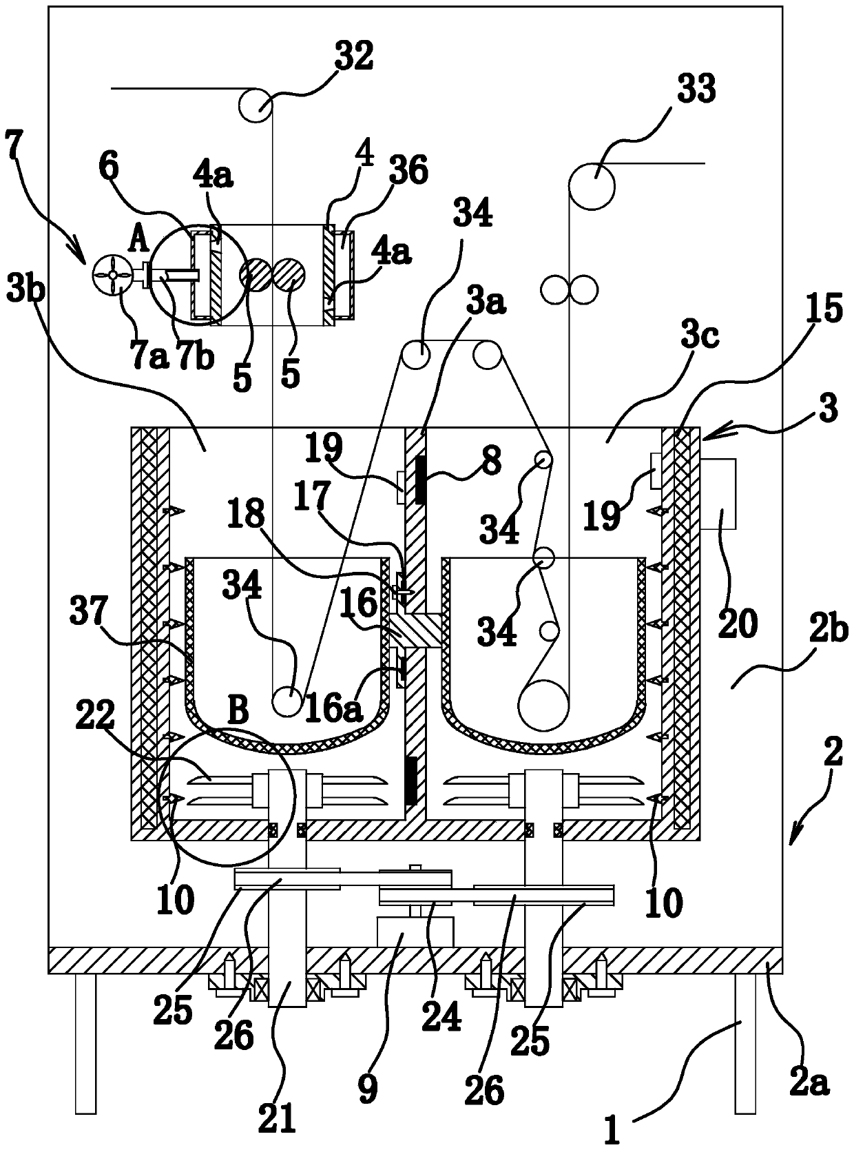
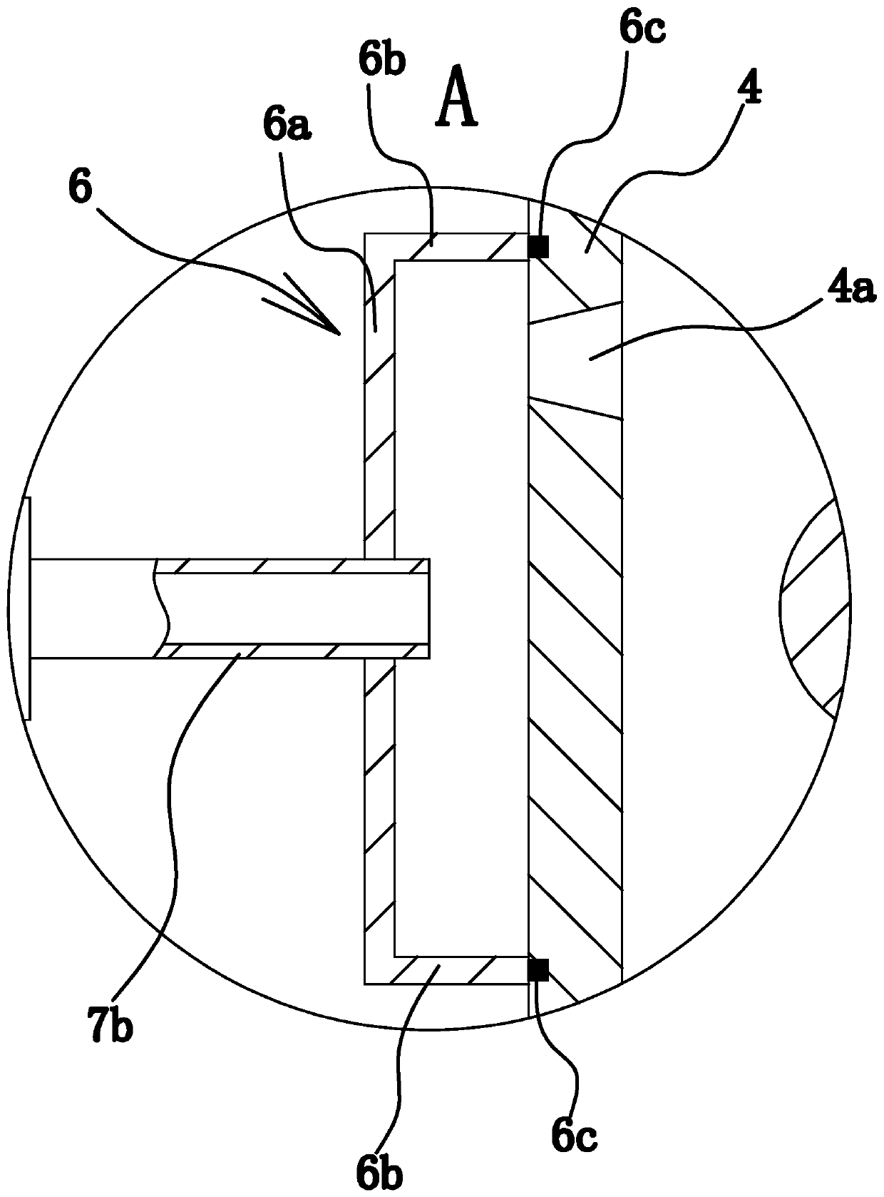
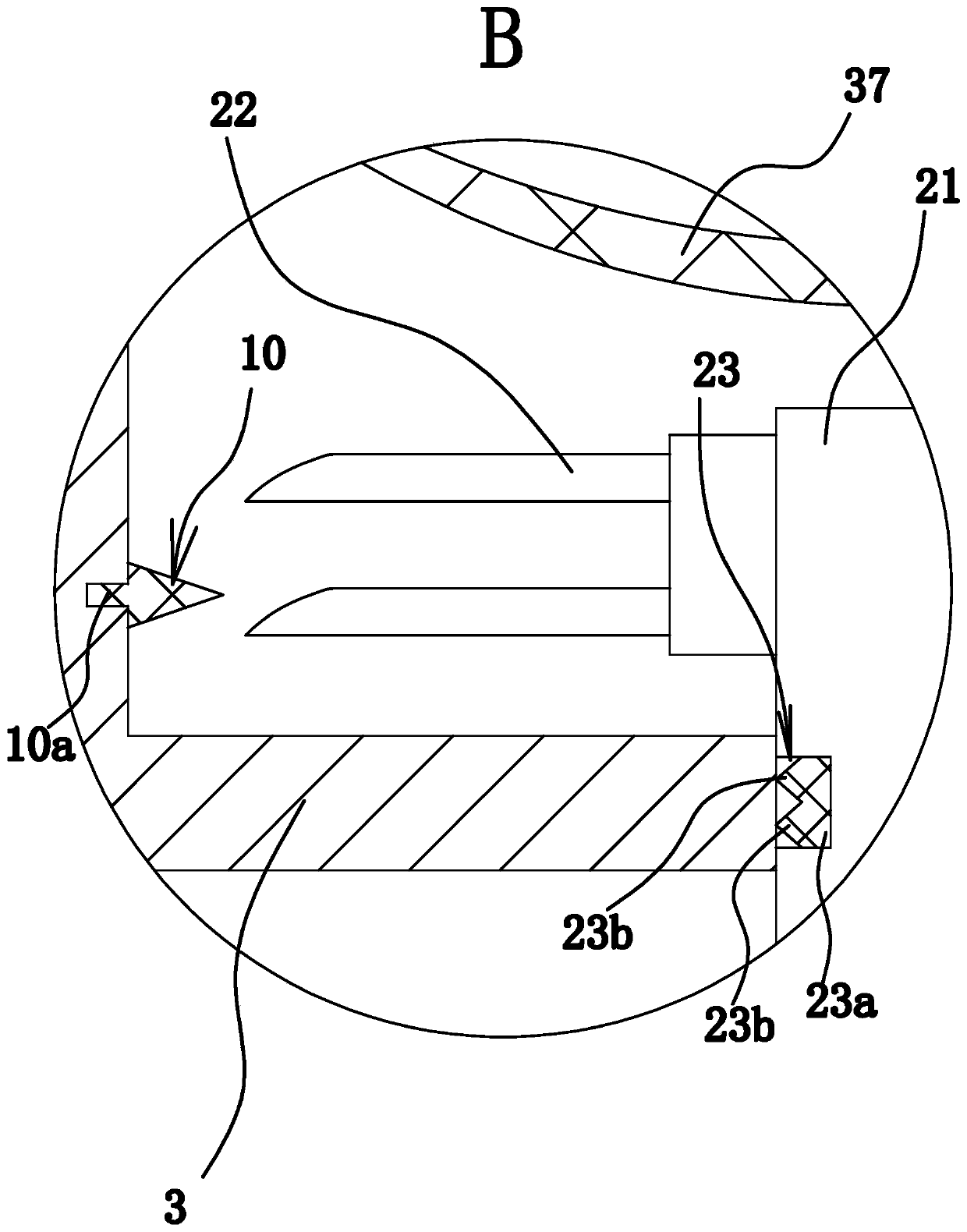
[0031] Such as Figure 1 to Figure 6 As shown, the glass fiber cloth gluing device consists of a bracket 1, a workbench 2, a tank body 3, an air suction ring 4, a roller shaft 5, a sealing ring 6, a negative pressure piece 7, an electric heating plate 8, a motor 9, and a crushing head 10. Composition of support block 11, piston 12, push plate 13, spring 14, etc. Wherein, the electric heating plate 8 is an existing product, which can be bought in the market.

[0032] Specifically, the workbench 2 is located on the support 1, such as figure 1 As shown, the workbench 2 is L-shaped, and the workbench 2 includes a horizontally arranged support part 2a and a vertically arranged support part 2b. Both the support part 2a and the support part 2b are plate-shaped, and the support part 1 2a is fixed to the bracket 1 by welding.

[0033] The tank body 3 is arranged on the front side of the workbench 2, and the notch of the tank body 3 faces upward. The tank body 3 and the supporting p...

Embodiment 2

[0058] The structure and principle of the present embodiment three are basically the same as those of the first embodiment, except that the motor 9 is located between the two stirring shafts 21, and the transmission mechanism includes a main gear fixed on the main shaft of the motor 9 and fixed on the two stirring shafts respectively. Two secondary gears on the 21, and both secondary gears are meshed with the main gear.


PUM


Abstract

The invention provides a stirring mechanism of a glass fiber cloth gluing device, which belongs to the technical field of machinery. It solves the problem of poor quality of existing gluing devices. In the present invention, the glass fiber cloth gluing device includes a bracket and a workbench fixed on the bracket. The workbench is fixed with a tank body with a notch upward, and the tank body has a glue tank that divides its inner cavity into mutually independent glue tanks and glue tanks. The separator of liquid tank 2, the stirring mechanism includes two stirring shafts vertically arranged in glue tank 1 and glue tank 2 respectively, the bottom of the tank body has a through hole, and there are two through holes, and the upper ends of the two stirring shafts are fixed There are stirring blades, the lower ends of the two stirring shafts pass through the two through holes respectively and are fixed axially with the workbench. The motor is also fixed on the workbench. The motor can drive the two stirring shafts to rotate through the transmission mechanism at the same time; A plurality of crushing heads are fixed on the inner wall of the second groove, and the crushing heads are conical. The stirring mechanism has the advantage of improving the gluing quality.

Description

technical field [0001] The invention belongs to the technical field of machinery, and relates to a glass fiber cloth gluing device, in particular to a stirring mechanism of the glass fiber cloth gluing device. Background technique [0002] Glass fiber is an inorganic non-metallic material with excellent performance. It has various types and has the advantages of good insulation, strong heat resistance, good corrosion resistance and high mechanical strength. [0003] The gluing process of glass fiber cloth is an important step in the processing of glass fiber cloth, and this process needs to be used in conjunction with the gluing device. Existing gluing devices such as the gluing equipment for glass fiber cloth disclosed in the Chinese Patent Library [Application No.: 201020597158.9; Authorized Announcement No.: CN 201864943 U] include a first accommodating groove to define a first accommodating space. to accommodate the first glue; a first roller, at least a part of which i...

Claims


Application Information

Patent Timeline
Patent Type & Authority Patents(China)
IPC IPC(8): B05C9/10B05C3/132B05C11/10B08B5/04B01F13/10B01F7/18
CPCB05C3/132B05C9/10B05C11/10B08B5/043B01F33/813B01F27/90B01F35/531
Inventor 沈海平
Owner 浙江凯澳新材料有限公司
Why Eureka
Try Eureka