Motor vehicle tail gas catalytic purifying device

A catalytic purification and motor vehicle technology, applied in exhaust devices, noise reduction devices, machines/engines, etc., can solve problems such as inapplicability to engine working conditions, shorten the service life of catalytic converters, and affect engine power, so as to improve conversion efficiency and utilization rate, avoid excessive catalytic strength, and improve catalytic efficiency and utilization rate

Active Publication Date: 2017-08-11
卢志旭
View PDF9 Cites 6 Cited by
  • Summary
  • Abstract
  • Description
  • Claims
  • Application Information

AI Technical Summary

Problems solved by technology

In the existing three-way catalytic converter, due to structural factors, when the exhaust gas flows through the carrier part of the three-way catalytic converter, the uniformity is unstable, and the best performance of the three-way catalytic converter cannot be brought out, and the transitional local catalytic strength Increased, shortening the service life of the catalytic converter
Design schemes to effectively improve flow uniformity have been proposed in some studies, but these improved device structures are often complex and cannot be applied to different engine operating conditions
Under certain working conditions, it will even cause a decrease in uniformity and a substantial increase in exhaust back pressure, which will affect the power of the engine

Method used


Image

  • Motor vehicle tail gas catalytic purifying device
  • Motor vehicle tail gas catalytic purifying device

Examples


Embodiment Construction

[0038] The present invention will be further described in detail below in conjunction with the accompanying drawings, so that those skilled in the art can implement it with reference to the description.

[0039] It should be noted that, in the description of the present invention, the terms "horizontal", "vertical", "upper", "lower", "front", "rear", "left", "right", "vertical", The orientation or positional relationship indicated by "horizontal", "top", "bottom", "inner", "outer", etc. is based on the orientation or positional relationship shown in the drawings, and is only for the convenience of describing the present invention and simplifying the description, and It is not to indicate or imply that the device or element referred to must have a particular orientation, be constructed in a particular orientation, or operate in a particular orientation, and thus should not be construed as limiting the invention.

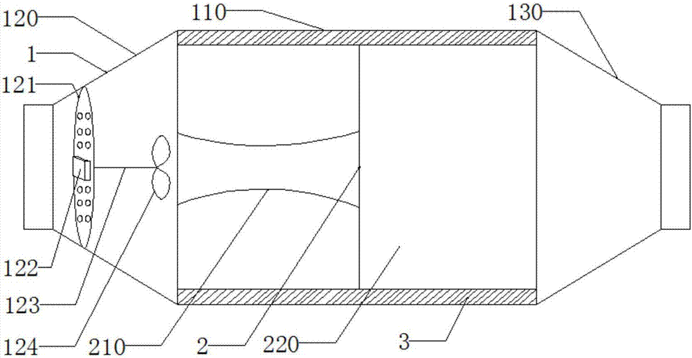
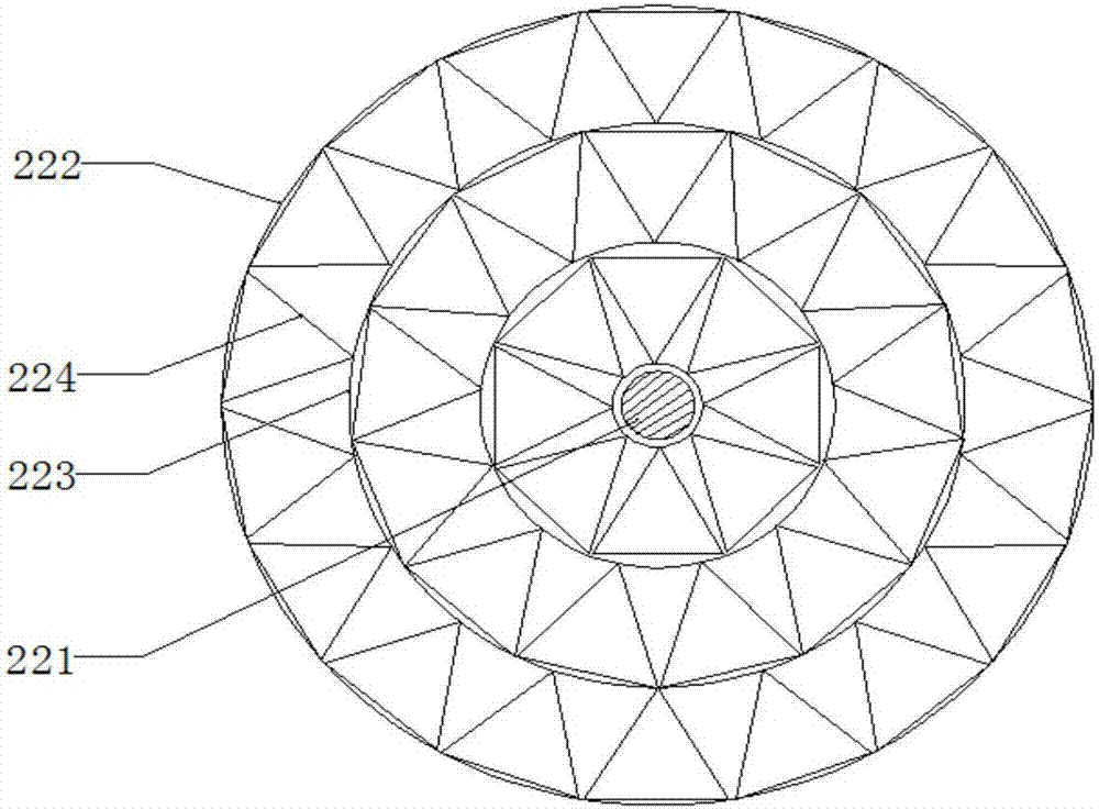
[0040] like Figure 1~2 As shown, the present invention provide...


PUM

PropertyMeasurementUnit
Concentrationaaaaaaaaaa

Abstract

The invention discloses a motor vehicle tail gas catalytic purifying device. The motor vehicle tail gas catalytic purifying device comprises a shell body and a catalyst carrier, wherein the shell body comprises a main body part, a gas inlet part and a gas outlet part, the gas inlet part and the gas outlet part are located on the two sides of the main body part, and the catalyst carrier is arranged in the main body part. The gas inlet part is internally provided with a gas guiding device. The gas guiding device comprises a deflector which is fixedly clamped in the gas inlet part, perpendicular to the gas inlet direction and provided with a plurality of gas guiding holes, and a gas flow stirring device which is fixed to the deflector. The gas flow stirring device comprises a driving device, a stirring rod and at least one pair of blades, wherein the driving device is fixedly arranged on the side, close to the gas inlet part, of the deflector; the stirring rod is connected with the driving device, penetrates through the deflector and extends to the side, away from the gas inlet part, of the deflector; and the blades are fixed to the end, away from the gas inlet part, of the stirring rod. According to the motor vehicle tail gas catalytic purifying device, through the combined action of the deflector and the gas flow stirring device, internal gas flowing is more uniform, and the time for internal gas to flow through the catalyst carrier is prolonged, so that catalytic reaction is more sufficient, thus, the conversion efficiency of the catalytic device is effectively improved, and the utilization rate of the catalytic device is effectively increased.

Description

technical field [0001] The invention relates to the technical field of motor vehicle exhaust emission. More specifically, the present invention relates to a catalytic purification device for exhaust gas of a motor vehicle. Background technique [0002] With the rapid development of the economy, people's demand for motor vehicles is increasing day by day, the production and ownership of domestic motor vehicles have increased sharply, and the problem of motor vehicle exhaust pollution has become more and more serious. Motor vehicle exhaust has become the main source of air pollutants. Motor vehicle pollution control measures are divided into two types of technologies: in-machine purification and out-of-machine control, among which catalytic converter is one of the most effective methods for purifying off-board exhaust gas. [0003] The existing three-way catalytic converter is an important part to improve automobile emission and reduce automobile exhaust pollution. The secon...

Claims


Application Information

Patent Timeline
IPC IPC(8): F01N3/28B01D53/94B01D53/56B01D53/62
CPCB01D53/945F01N3/28F01N3/2803F01N3/2828F01N3/2892Y02A50/20Y02T10/12
Inventor 卢志旭
Owner 卢志旭
Why Eureka
Try Eureka