Catalytic filter composite element and its preparation method and application

A composite element and catalytic filtration technology, which is applied in the direction of chemical instruments and methods, separation methods, and dispersed particle filtration, etc., can solve the problems of easy agglomeration and distribution of catalysts, unsatisfactory catalytic performance, and high price, so as to achieve short preparation cycle and reduce production cost. Cost and operating pressure drop, effect of increased reactivity

Active Publication Date: 2022-07-29
CHINA UNIV OF PETROLEUM (BEIJING)
View PDF7 Cites 0 Cited by
  • Summary
  • Abstract
  • Description
  • Claims
  • Application Information

AI Technical Summary

Problems solved by technology

However, this type of catalytic composite filter element has problems such as large pressure drop, unsatisfactory catalytic performance, short life and high price, which are mainly attributed to the low porosity (<40%) and high brittleness of the prepared filter element. Catalysts are easy to agglomerate and unevenly distributed

Method used


Image

  • Catalytic filter composite element and its preparation method and application
  • Catalytic filter composite element and its preparation method and application
  • Catalytic filter composite element and its preparation method and application

Examples


Embodiment 1

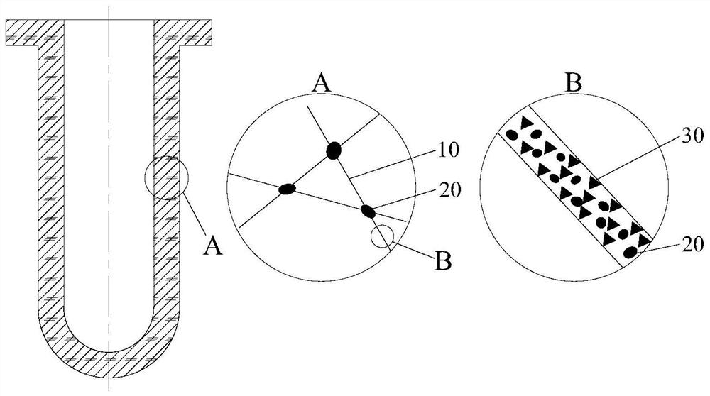
[0056] The present embodiment provides a catalytic filter composite element, the preparation method of which includes:

[0057] 1. Based on the total mass of the slurry as 100%, 2% aluminum silicate fiber, 0.5% sodium carboxymethyl cellulose, 97.5% (by mass of silica) silica sol were stirred in a high-speed disperser for 90min to form Homogeneous slurry. The slurry is injected into the mold, and most of the liquid is removed from the mold by vacuum suction. When most of the liquid in the slurry is removed, the speed of the vacuum suction gas is 10m / min-12m / min ; Take out when the slurry is formed and no liquid leaks out, put the formed slurry in a microwave dryer with 700W power and dry to constant weight, at this time the silica sol inside the slurry is completely dried and solidified to form a rigid structure; then 600 ℃ After calcining for 3 hours, the heating rate during the calcination was 10°C / min, and after returning to room temperature, the substrate was taken out to ...

Embodiment 2

[0064] This embodiment provides a preparation method of a catalytic filter composite element. Compared with embodiment 1, the only difference is that the power of microwave drying in step 2 is 231W, and other experimental steps and experimental parameters are the same as those in embodiment 1.

Embodiment 3

[0066] This embodiment provides a preparation method of a catalytic filter composite element. Compared with embodiment 1, the only difference is that the power of microwave drying in step 2 is 700W, and other experimental steps and experimental parameters are the same as those in embodiment 1.


PUM

PropertyMeasurementUnit
diameteraaaaaaaaaa
specific surface areaaaaaaaaaaa

Abstract

The invention provides a catalytic filter composite element and a preparation method and application thereof. The preparation method includes mixing ceramic fibers, silica sol and dispersant to form a uniform slurry, mixing the slurry into a mold, demoulding after molding, drying and calcining to obtain a base material; immersing the base material in a first The solution is kept in a vacuum for a period of time, taken out, microwave-dried, and roasted to obtain an intermediate element; the intermediate element is immersed in the second solution, kept in a vacuum for a period of time, taken out, microwave-dried, and roasted to obtain the catalytic filter composite element. The present invention further provides the catalytic filter composite element obtained by the above preparation method and its application in the synergistic removal of particulate matter and NOx. The above composite element has large pores, high toughness, large specific surface area, low pressure drop, high filtration efficiency and high catalytic activity.

Description

technical field [0001] The invention relates to the technical field of high-temperature flue gas integrated purification, in particular to a catalytic filter composite element and a preparation method and application thereof. Background technique [0002] With the continuous improvement of flue gas emission standards and the increasingly severe environmental protection situation, the comprehensive treatment and purification of combustion flue gas pollutants has become the top priority in the field of energy and environment in my country. In many fields such as coal-fired power generation, petrochemical industry, metallurgy, and waste incineration, dust particles and nitrogen oxides (NOx) in flue gas are emitted. x ) is the main component of air pollutants and the root cause of a series of environmental problems such as haze, photochemical smog and acid rain. In the traditional high-temperature flue gas purification process, dust removal and catalytic denitrification are two...

Claims


Application Information

Patent Timeline
Patent Type & Authority Patents(China)
IPC IPC(8): B01J23/30B01J35/10B01J35/02B01D53/86B01D53/56B01D46/24
CPCB01J23/30B01J35/1004B01J35/023B01D53/8628B01D46/2411B01D2258/0283
Inventor 吴小林苗林丰姬忠礼常程刘震陈锋
Owner CHINA UNIV OF PETROLEUM (BEIJING)
Why Eureka
Try Eureka