Method for detecting depth of subsurface crack of optical material

A technology of optical materials and detection methods, applied in the direction of optical testing flaws/defects, preparation of test samples, etc., to achieve the effect of improving detection efficiency

Inactive Publication Date: 2017-08-11
ZHEJIANG NORMAL UNIVERSITY
View PDF7 Cites 12 Cited by
  • Summary
  • Abstract
  • Description
  • Claims
  • Application Information

AI Technical Summary

Problems solved by technology

[0005] The purpose of the present invention is to use laser confocal microscopy to overcome the defects of the current angle polishing method to detect the depth of subsurface cracks, and to provide an efficient, high-precision, and convenient detection method for the depth of subsurface cracks in optical materials

Method used


Image

  • Method for detecting depth of subsurface crack of optical material
  • Method for detecting depth of subsurface crack of optical material
  • Method for detecting depth of subsurface crack of optical material

Examples


Embodiment 1

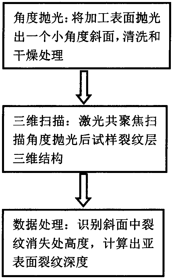
[0023] The subsurface crack depth detection method of K9 glass after abrasive grain processing, the detection process of this method is as follows figure 1 shown, including the following steps:

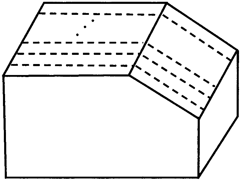
[0024] (1) Angle polishing: Bond the K9 glass sample to be tested on the angle polishing fixture, put it into a biaxial polishing machine, and use diamond micropowder with a particle size of W1 and cerium oxide polishing solution with a particle size of 0.5 μm for grinding. and polishing, the design angle of the angle polishing fixture is 6°; after grinding and polishing, the sample is etched in 1% HF solution for 5 minutes, taken out for ultrasonic cleaning, and then put into a vacuum drying oven for drying;

[0025] (2) Three-dimensional scanning: Olympus OLS4500 laser confocal microscope (Z-direction resolution 10nm) was used to perform three-dimensional tomographic scanning on the sample after angle polishing to obtain the three-dimensional structure of the crack layer;

[0026] ...

Embodiment 2

[0029] The subsurface crack depth detection method of the Si wafer after abrasive grain processing, the detection process of this method is as follows figure 1 shown, including the following steps:

[0030] (1) Angle polishing: the Si wafer sample to be measured is bonded on an angle polishing fixture, put into a biaxial lapping machine for grinding and chemical mechanical polishing, and the design angle of the angle polishing fixture is 6°; grinding and polishing Finally, put the sample into the "Young's" solution to etch for 30s, take it out for ultrasonic cleaning, and then put it in a vacuum drying oven to dry;

[0031] (2) Three-dimensional scanning: Olympus OLS4500 laser confocal microscope (Z-direction resolution 10nm) was used to perform three-dimensional tomographic scanning on the sample after angle polishing to obtain the three-dimensional structure of the crack layer;

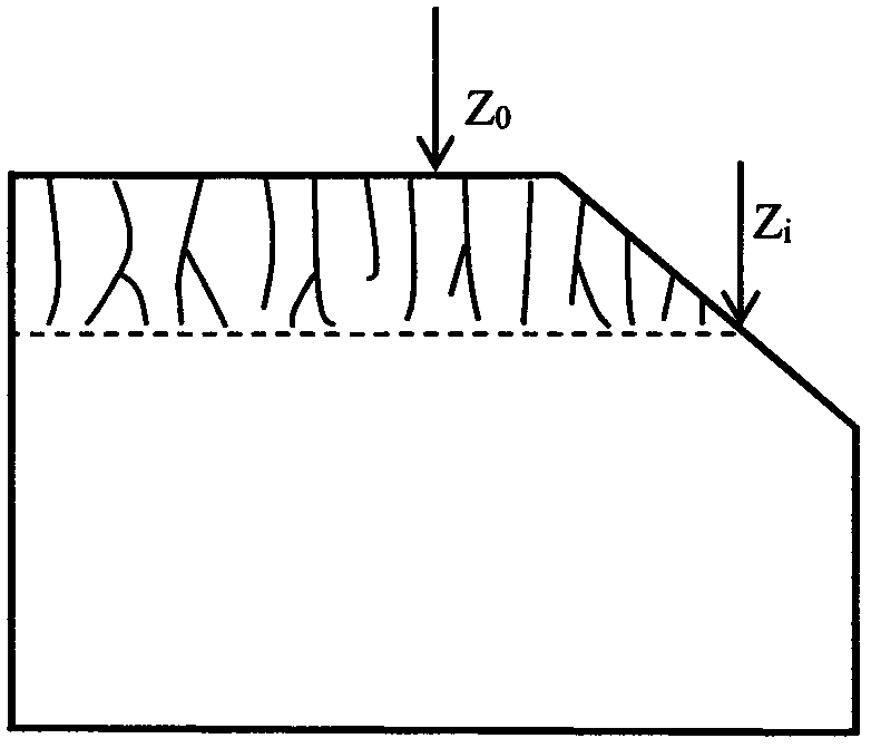
[0032] (3) Data processing: Since the measured object is a non-transparent material, the three-...


PUM

PropertyMeasurementUnit
particle diameteraaaaaaaaaa

Abstract

The invention discloses a method for detecting depth of a subsurface crack of an optical material. The method comprises the following steps: polishing one small-angle inclined plane on a sample surface subjected to abrasive machining by adopting an angle method, and corroding the sample surface and the inclined plane by utilizing a specific etching liquid, thereby guaranteeing that a surface polishing deposited layer is removed; carrying out three-dimensional scanning on a sample subjected to angle polishing by utilizing a laser confocal microscopy, and obtaining a three-dimensional chromatography structure of a crack layer of the sample; and converting the three-dimensional structure of the crack layer into a two-dimensional graph, carrying out data processing, and finally obtaining the depth of the subsurface crack of the to-be-detected material. The method disclosed by the invention overcomes the defects of an existing angle polishing method used for detecting the depth of the subsurface crack by utilizing a laser confocal microtechnique and is efficient, high in precision and portable when being used for detecting the depth of the subsurface crack of the optical material.

Description

technical field [0001] The invention relates to a method for detecting the depth of subsurface cracks in optical materials, in particular to a method for detecting the depth of subsurface cracks in optical materials after abrasive grain processing. Background technique [0002] Subsurface cracks caused by abrasive grain processing of optical materials reduce the service stability and life of optical components by reducing the laser damage threshold and mechanical properties. Therefore, accurate and efficient detection of the subsurface crack depth of optical materials becomes the key to optimize the processing technology and remove the damaged layer. [0003] At present, the subsurface damage detection methods of optical materials are mainly divided into two categories: non-destructive detection methods and destructive detection methods. The non-destructive testing method is a method of quantitatively evaluating the integrity of materials by using physical principles such a...

Claims


Application Information

Patent Timeline
Patent Type & Authority Applications(China)
IPC IPC(8): G01N21/95G01N1/32
CPCG01N1/32G01N21/95
Inventor 王华东黄平何力钧庞佩
Owner ZHEJIANG NORMAL UNIVERSITY
Why Eureka
Try Eureka