vacuum cleaner impeller
A technology for vacuum cleaners and impellers, applied in vacuum cleaners, machines/engines, liquid fuel engines, etc., can solve the problems of increasing the cooling load and noise of the fan, reducing the energy conversion rate of the fan, etc., to reduce the axial eddy current, improve the energy conversion efficiency, The effect of reducing the possibility of resonance
- Summary
- Abstract
- Description
- Claims
- Application Information
AI Technical Summary
Problems solved by technology
Method used
Image

Examples
Embodiment 1
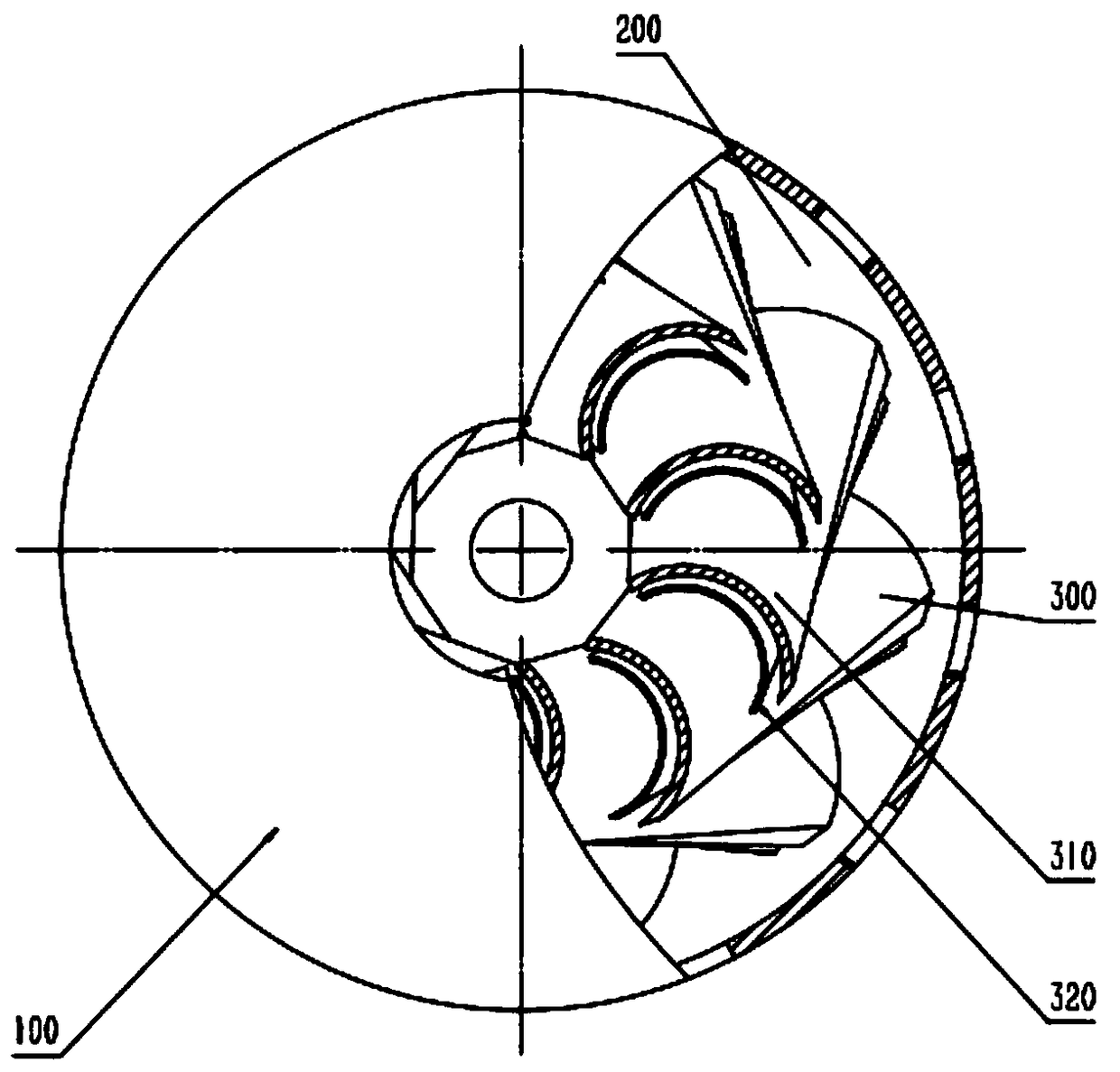
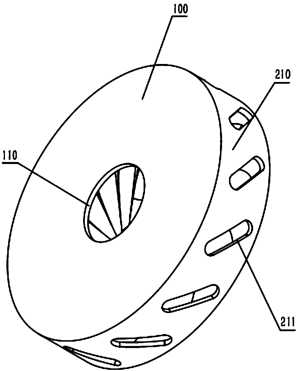
[0032] Combine Figure 1-2 As shown, a vacuum cleaner impeller includes at least: a front wheel cover 100, which is a disc structure, the middle of the front wheel cover 100 is provided with a first through hole 110; a rear wheel cover 200, which is a disc structure, the The edge of the rear wheel cover 200 is fixedly connected to the outer edge of the front wheel cover 100 through a deflector 210 with a cylindrical shell structure. The deflector 210 is provided with a plurality of second through holes 211; and the blade 300 is fixed. Disposed between the front wheel cover 100 and the rear wheel cover 200, the blade 300 includes a plurality of main blades 310 and a plurality of splitter blades 320. The main blades 310 extend from the front wheel cover 100 in the radial direction. The edge of the first through hole extends outward to a first predetermined distance from the outer edge of the front wheel cover 100, and the main blade 310 extends from the rear side wall of the fron...
Embodiment 2
[0035] The dividing blades 320 are arranged non-uniformly, and the distance between the two adjacent groups of dividing blades 320 and the corresponding main blade 310 with the closest distance is not equal. The distance between the dividing blade 320 and the closest main blade 310 is not less than one tenth of the distance between two adjacent groups of main blades 310. The dividing blade 320 cuts each air flow channel between the main blades 310. If the air flow channels formed by the division are the same size, the air at the outlet of the air flow channel will easily resonate due to the similar movement state. It produces louder noise and reduces the energy conversion efficiency of the fan. Therefore, by controlling the position of the splitter blade 320 to make the divided air flow passages different to avoid the above problems, at the same time, the splitter blade 320 should not be too close to the main blade 310, otherwise it is easy for air to quickly pass through this ...
Embodiment 3
[0037] The second through holes 211 on the flow deflector 210 are in an elliptical shape, and the second through holes 211 are evenly distributed. The number of the second through holes 211 corresponds to the main blade 310 one by one, and the ellipse is long The angle between the shaft and the generatrix of the cylindrical shell is 0.5-0.7 times the first angle. The inclination direction of the second through hole 211 is consistent with the inclination direction of the main blade 310. The guide cover 210 is provided with the second through hole 211 to further guide the airflow discharged from the impeller blades, so as to reduce the turbulent flow of the air after passing through the air flow channel formed by the blades, thereby improving The stability of the overall fan.
PUM
 Abstract
Description
Claims
Application Information
 - R&D
- Intellectual Property
- Life Sciences
- Materials
- Tech Scout
- Unparalleled Data Quality
- Higher Quality Content
- 60% Fewer Hallucinations
Browse by: Latest US Patents, China's latest patents, Technical Efficacy Thesaurus, Application Domain, Technology Topic, Popular Technical Reports.
© 2025 PatSnap. All rights reserved.Legal|Privacy policy|Modern Slavery Act Transparency Statement|Sitemap|About US| Contact US: help@patsnap.com