Switched reluctance motor current tracking control method, controller and speed adjusting system

A switched reluctance motor and current tracking technology, applied in the control system, vector control system, motor generator control and other directions, can solve the problem of ignoring the mutual inductance effect, improve the current tracking accuracy, the control method is simple and easy, and the reliability strong effect

Active Publication Date: 2017-08-15
HUNAN UNIV
View PDF3 Cites 5 Cited by
  • Summary
  • Abstract
  • Description
  • Claims
  • Application Information

AI Technical Summary

Problems solved by technology

[0004] Therefore, it is necessary to design a new switched reluctance motor control method for the shortcomings of the above-mentioned traditional current hysteresis control and the existing control method ignoring the mutual inductance effect.

Method used


Image

  • Switched reluctance motor current tracking control method, controller and speed adjusting system
  • Switched reluctance motor current tracking control method, controller and speed adjusting system
  • Switched reluctance motor current tracking control method, controller and speed adjusting system

Examples


Embodiment 1

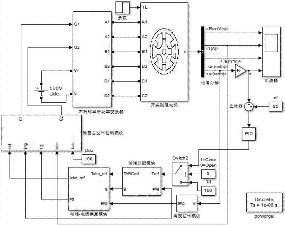
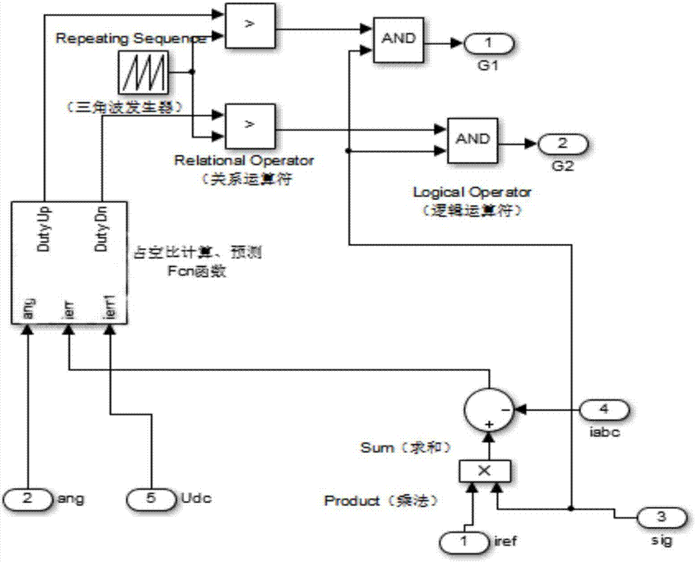
[0035] based on figure 1 with figure 2 In the simulink simulation model shown, the electrical equation of the k-th phase winding is:

[0036]

[0037] s(j) is the energization state of the k-th phase winding in the j-th control cycle, and the value is 1, -1 or 0, corresponding to the three states of positive pressure, negative pressure and zero voltage respectively. For 8 / 6 switching magnetic For a resistance motor, k represents any of the four phases of A, B, C, and D, and for a 6 / 4 switched reluctance motor, k represents any of the three phases of A, B, and C. Derived from equation (1), the current equation of the k-phase winding at time t is:

[0038]

[0039] Among them, θ is the rotor position angle at time t, U dc Is the bus voltage, L k (θ) is the average value of the inductance of the k-phase winding in the next control period T, R is the resistance value of the k-phase winding, and ω is the actual speed of the switched reluctance motor.

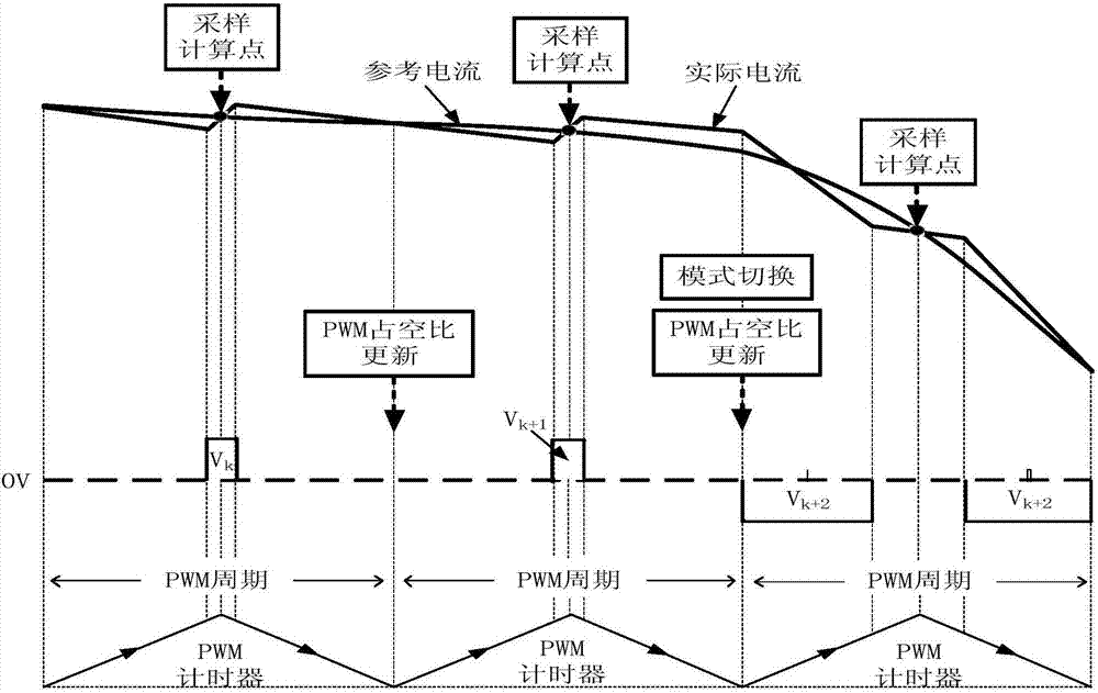
[0040] Such as image 3 As shown...


PUM


Abstract

The invention discloses a switched reluctance motor current tracking control method, a switched reluctance motor current tracking controller and a switched reluctance motor speed adjusting system. The switched reluctance motor current tracking control method comprises the steps that: a voltage duty ratio of each control cycle is calculated according to positive and negative as well as magnitude of current deviation signals, and the updating of a control quantity is realized; and a voltage control quantity output at a phase changing stage further takes mutual inductance influence of adjacent opposing conduction phases into account. The switched reluctance motor current tracking control method, the switched reluctance motor current tracking controller and the switched reluctance motor speed adjusting system improve the current tracking precision at low-control frequency, achieve the effect of high switching frequency, enhance the current dynamic tracking capacity, and effectively decrease torque ripples during a phase-changing period and a non-phase-changing period; and a switching device does not need to be exposed to high current under the situation that the power device switching frequency is limited, and the control method is simple and feasible, high in reliability and suitable for popularization.

Description

Technical field [0001] The invention relates to the field of motor control, in particular to a current tracking control method, a controller and a speed regulation system of a switched reluctance motor. Background technique [0002] Switched reluctance motor (SRM) is considered to be a highly potential member in the field of variable speed drive due to its simple structure, reliable operation, large starting torque and high mechanical efficiency. However, due to the double salient structure of the stator and rotor, the phase inductance changes significantly with the rotor position, which makes the switched reluctance motor have the characteristics of no precise mathematical model and severe nonlinearity, and it is difficult to achieve precise control of its phase current. The suppression of torque ripples largely depends on the control accuracy of the phase winding currents. Therefore, it is urgent to design a current controller with high tracking performance. [0003] When the co...

Claims


Application Information

Patent Timeline
Patent Type & Authority Applications(China)
IPC IPC(8): H02P21/22H02P25/098
Inventor 李孟秋蔡辉史林然王辉罗德荣刘平
Owner HUNAN UNIV
Why Eureka
Try Eureka