A switched reluctance motor current tracking control method, controller and speed regulating system
A switched reluctance motor and current tracking technology, which is applied in control systems, vector control systems, motor generator control, etc., can solve problems such as ignoring mutual inductance effects, achieve improved current tracking accuracy, strong reliability, and simple and easy control methods line effect
- Summary
- Abstract
- Description
- Claims
- Application Information
AI Technical Summary
Problems solved by technology
Method used
Image
Examples
Embodiment 1
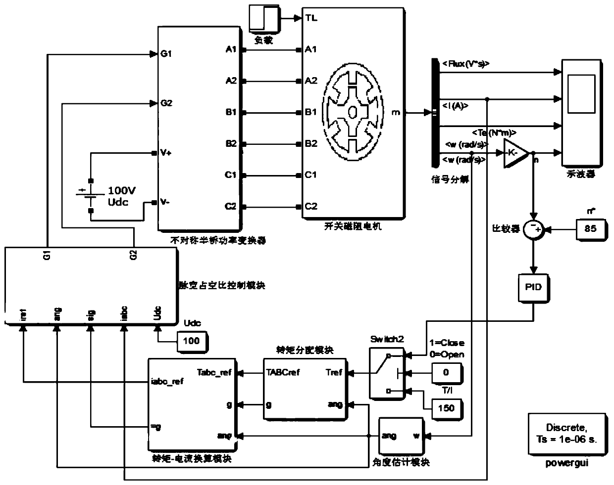
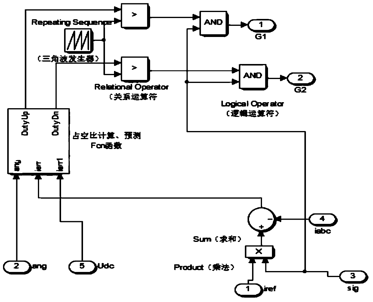
[0035] based on figure 1 and figure 2 In the simulink simulation model shown, the electrical equation of the kth phase winding is:
[0036]
[0037]s(j) is the energized state of the k-th phase winding in the j-th control cycle, and the value is 1, -1 or 0, which correspond to the three states of positive pressure, negative pressure and zero pressure respectively. For 8 / 6 switching magnetism For a resistance motor, k represents any of the four phases A, B, C, and D, while for a 6 / 4 switched reluctance motor, k represents any of the three phases A, B, and C. The current equation of the k-phase winding at time t is derived from formula (1):
[0038]
[0039] Among them, θ is the rotor position angle at time t, U dc is the bus voltage, L k (θ) is the average value of the inductance of the k-phase winding in the next control period T, R is the resistance value of the k-phase winding, and ω is the actual speed of the switched reluctance motor.
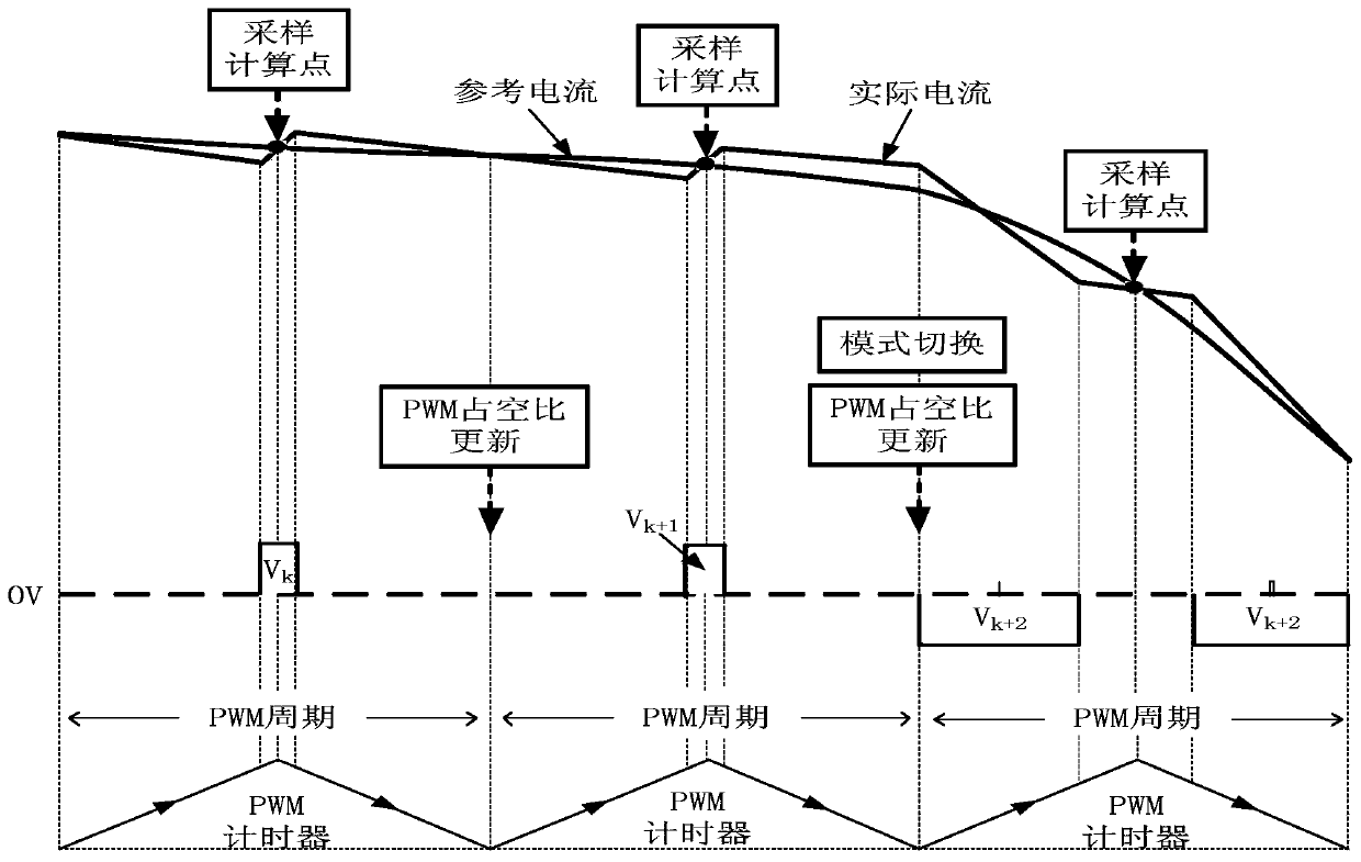
[0040] Such as image 3...
PUM
 Abstract
Description
Claims
Application Information
 - R&D
- Intellectual Property
- Life Sciences
- Materials
- Tech Scout
- Unparalleled Data Quality
- Higher Quality Content
- 60% Fewer Hallucinations
Browse by: Latest US Patents, China's latest patents, Technical Efficacy Thesaurus, Application Domain, Technology Topic, Popular Technical Reports.
© 2025 PatSnap. All rights reserved.Legal|Privacy policy|Modern Slavery Act Transparency Statement|Sitemap|About US| Contact US: help@patsnap.com


