PCR micro-fluidic chip and preparation and using methods thereof and PCR equipment

A microfluidic chip and equipment technology, applied in chemical instruments and methods, laboratory containers, laboratory utensils, etc., can solve the problems of limited sample volume, uneven temperature, inability to adjust, etc., and achieve simple temperature control methods , easy system integration, simple design effect

Inactive Publication Date: 2017-08-18
SHANGHAI JIAO TONG UNIV
View PDF3 Cites 11 Cited by
  • Summary
  • Abstract
  • Description
  • Claims
  • Application Information

AI Technical Summary

Problems solved by technology

Since the volume of the external heating block is usually large and the specific heat is large, it takes a long time (30-60s) for the reaction liquid to reach the set temperature, thus making the entire reaction time longer
[0011] 2. Uneven temperature of the reaction solution: Since the temperature of the external heating block itself is very uneven, and the volume of the reaction solution is large (20-100μL), when the set temperature is to be reached, there is a temperature gradient in the reaction solution, which makes uneven temperature
The average temperature difference between the upper and lower parts of a general PCR reaction tube will reach 10°C, which will greatly reduce the annealing efficiency of primers and the specificity of amplification.
[0012] 3. Large consumption of biochemical reagents: The large volume of reaction tubes of conventional instruments increases the consumption of biochemical reagents, making the reaction very expensive, but it is very difficult to operate small volume samples with conventional instruments
[0019] However, although the existing PCR chip can reduce the consumption of the mixed solution, its temperature cycle still depends on the heating / cooling rate of the temperature control system, so the amplification speed is still relatively slow, and the temperature control system has a complex structure and a large volume. It is relatively large, which limits the volume of the sample and cannot be adjusted according to different needs. Moreover, since the heater and cooler must be integrated with the chip, the cost of chip production is relatively high, which has become the biggest obstacle to further commercial applications in the future.

Method used


Image

  • PCR micro-fluidic chip and preparation and using methods thereof and PCR equipment
  • PCR micro-fluidic chip and preparation and using methods thereof and PCR equipment
  • PCR micro-fluidic chip and preparation and using methods thereof and PCR equipment

Examples


Embodiment 1

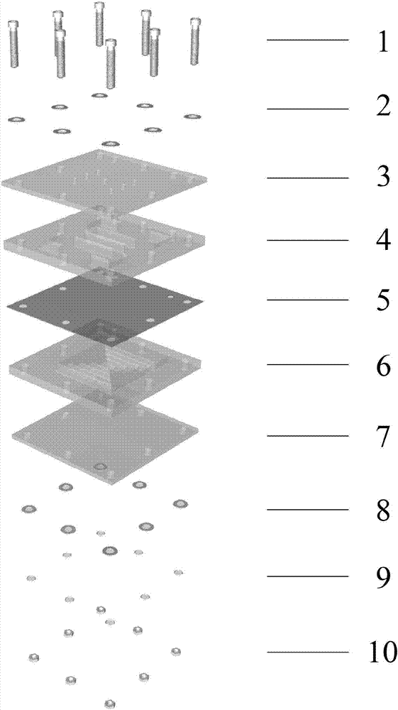
[0057] figure 1 A specific embodiment of the PCR microfluidic chip involved in the present invention is shown. In this embodiment, the PCR microfluidic chip includes an upper sealing layer 3 , a sample layer 4 , a heat transfer layer 5 , a thermal fluid layer 6 and a lower sealing layer 7 which are stacked sequentially from top to bottom. The above five layers are fastened together by the hexagon socket bolt 1 , the upper flat pad 2 , the lower flat pad 8 , the spring washer 9 and the nut 10 . The heat transfer layer 5 is copper foil or other heat transfer materials. Copper foil thickness is 100μm, or other thickness.

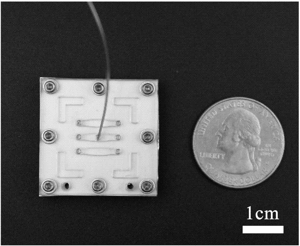
[0058] Three parallel oval sample cavities are arranged on the sample layer 4 . The oval sample chamber in the middle is connected to a thermocouple. Four L-shaped hollows are also arranged on the sample layer 4 . Since the upper sealing layer 3 is made of transparent plexiglass, the above-mentioned structure of the sample layer 4 can be seen from the fron...

Embodiment 2

[0062] In this embodiment, the PCR microfluidic chip includes a sample layer, a heat transfer layer, and a thermal fluid layer that are stacked sequentially from top to bottom. Since the top of the sample chamber and the bottom of the thermal channel are not cut through during processing, no additional upper and lower sealing layers are required. Others are the same as in Example 1.

Embodiment 3

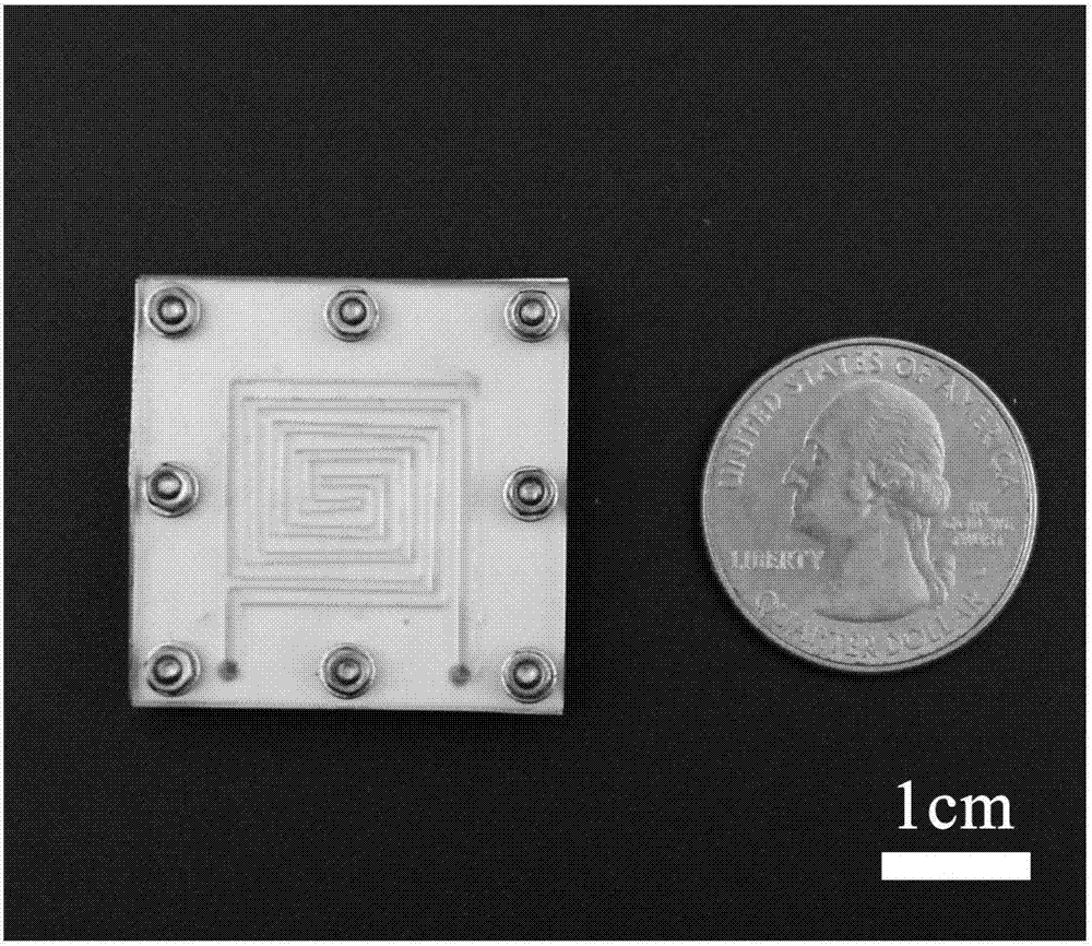
[0064] Figure 4 Another specific embodiment of the PCR microfluidic chip involved in the present invention is shown. In this embodiment, the PCR microfluidic chip includes a sample cavity 41 and a heat conduction channel 61 . The sample cavity 41 is arranged around the heat conduction channel 61 , both of which are on the same plane without stratification. The sample chamber 41 is elliptical, and there are two in number, one of which is connected to the thermocouple 502, but the shape and number of the sample chamber 41 are not limited thereto. The heat conduction channel 61 is S-shaped, but not limited thereto.


PUM


Abstract

The invention discloses a PCR micro-fluidic chip which comprises a sample cavity and a heat-conducting channel; a heat-conducting liquid is arranged in the heat-conducting channel; and the heat-conducting liquid can absorb infrared rays. The invention also discloses preparation and using methods of the chip as well as PCR equipment comprising the chip. The PCR equipment also comprises a PCR temperature control platform which comprises a peristaltic pump, a fuel tank, an infrared light source, a data collecting card, a thermocouple, a thermocouple cold end compensating circuit and a power supply circuit board for controlling the infrared ray light source and the peristaltic pump. The PCR micro-fluidic chip disclosed by the invention is simple in design, convenient to process, saved in step and low in cost; and the PCR temperature control platform is simple in temperature control mode, convenient to integrate systematically, and convenient to use and carry.

Description

technical field [0001] The invention relates to the field of consumables and equipment related to DNA amplification, in particular to a PCR microfluidic chip, its preparation and use method, and a PCR equipment. Background technique [0002] PCR, translated into Chinese as polymerase chain reaction, is a rapid amplification technology of DNA. PCR technology can increase the amount of specific DNA by 10 million times within 3 hours through the action of two short DNA fragments called primers and a heat-resistant enzyme. PCR technology has made a breakthrough in molecular biology research, and with the improvement of PCR technology, the application of PCR in human social life is becoming more and more extensive. For example, in "DNA fingerprinting", scientists only need a hair or even a cell to complete the identification of DNA fingerprinting. In fact, PCR technology is used here, because the DNA content in a cell is very low, and it is not easy to directly Its fingerprint ...

Claims


Application Information

Patent Timeline
Patent Type & Authority Applications(China)
IPC IPC(8): B01L3/00
CPCB01L3/502707
Inventor 刘文佳丁显廷
Owner SHANGHAI JIAO TONG UNIV
Why Eureka
Try Eureka