Radiation type rotary drying device for waste salt treatment

A technology of rotary drying and salt treatment, applied in non-progressive dryers, heating devices, drying solid materials, etc., can solve the problems of inability to achieve organic matter removal effect, affect treatment steps, low temperature, etc., and achieve constant temperature and uniform heating , to ensure the effect of flue gas flow rate

Pending Publication Date: 2017-08-18
安徽今朝环保科技有限公司
View PDF3 Cites 9 Cited by
  • Summary
  • Abstract
  • Description
  • Claims
  • Application Information

AI Technical Summary

Problems solved by technology

It is necessary to heat the waste salt to a very high temperature to ensure that as much organic matter as possible is decomposed or vaporized, but the fine-grained waste salt is prone to melting during the heating process, and once it melts, serious agglomeration will occur , seriously affecting the subsequent processing steps
The temperature control is too low, and the effective organic matter removal effect cannot be achieved. Therefore, how to increase the heating temperature as much as possible in this process and ensure the stability and uniformity of the heating temperature is a very important issue.

Method used


Image

  • Radiation type rotary drying device for waste salt treatment
  • Radiation type rotary drying device for waste salt treatment
  • Radiation type rotary drying device for waste salt treatment

Examples


Embodiment 1

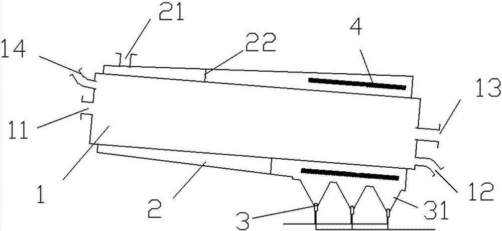
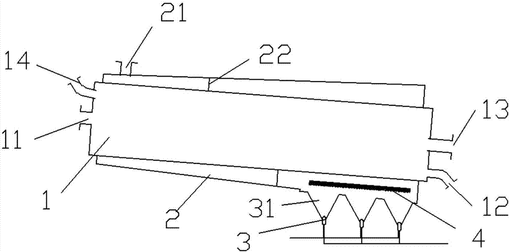
[0019] like figure 1 and 2 As shown, a radiant rotary drying device for waste salt treatment includes a rotary barrel 1, which is arranged obliquely, and a feed port is provided on the end face of the higher end of the rotary barrel 1 11 and the exhaust port 14, the discharge port 12 and the air inlet 13 are provided on the end face of the lower end of the rotary barrel 1, and the feature is that a heating jacket 2 is also provided on the outside of the rotary barrel 1 , the heating jacket 2 is fixed and does not rotate with the rotary barrel 1, the inclination direction and angle of the heating jacket 2 and the rotary barrel 1 are the same, and a burner 3 is arranged below the lower end of the heating jacket 2 , the flame nozzle 31 of the burner 3 is connected to the inner cavity of the heating jacket 2, and a heat radiation plate 4 is also arranged in the heating jacket 2, and the heat injection port of the burner 3 points directly to the heat radiation plate 4. Commonly u...

Embodiment 2

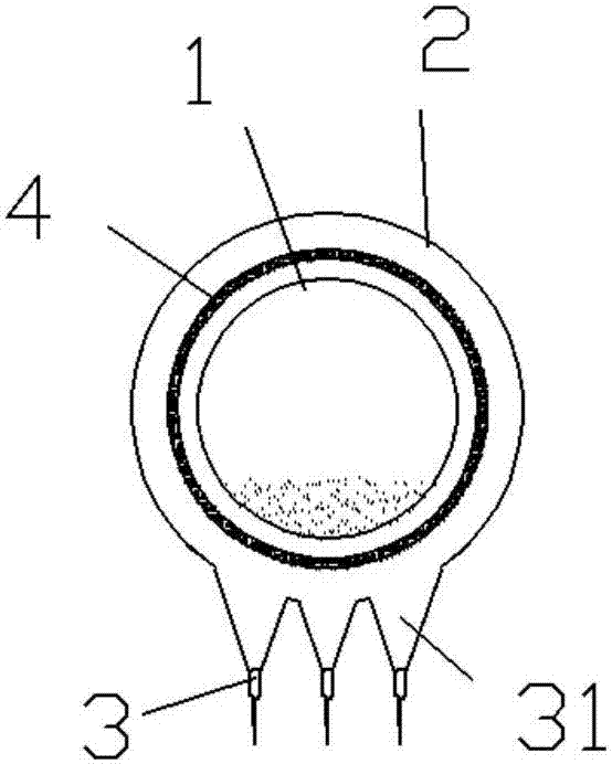
[0026] like image 3 and 4 As shown, the heat radiation plate 4 surrounds the heating jacket 2 in a cylindrical shape, the heat radiation plate 4 rotates synchronously with the rotating cylinder, and the heat radiation plate 4 and the rotating cylinder are arranged concentrically. The synchronously rotating heat radiation plate 4 can effectively disperse the heat of the flame and then conduct radiation heat transfer to the rotating cylinder. The temperature of the flame is generally significantly higher than the melting temperature of the waste salt, which will cause the temperature of the heat radiation plate 4 to be too high, making the temperature It is difficult to control. By rotating the heat radiation plate 4, the temperature of the flame is diluted and dispersed around the rotating cylinder to ensure uniform and stable heat supply. At the same time, the temperature of the heat radiation plate 4 can be conveniently adjusted to effectively control Waste salt treatment p...


PUM


Abstract

The invention discloses a radiation type rotary drying device for waste salt treatment. The radiation type rotary drying device comprises a rotary material cylinder. A heating jacket is arranged on the outer side of the rotary material cylinder. The heating jacket and the rotary material cylinder are the same in inclination direction and inclination angle. A burner is arranged below the lower end of the heating jacket. A flame spray opening of the burner is connected with an inner cavity of the heating jacket. A heat radiation plate is arranged in the heating jacket. A heat jet opening of the burner directly faces the heat radiation plate. Compared with the prior art, the radiation type rotary drying device has the following beneficial effects that the energy of flames is absorbed by the heat radiation plate, and then the heat is transmitted to the rotary material cylinder in a heat radiation manner, so that the rotary material cylinder is uniformly heated, and the temperature is quite constant; the heating jacket is fixedly arranged, and a rotary cylinder body rotates in the heating jacket, so that the heating of the whole rotary cylinder body is consistent in the radial direction; and the flue gas flow speed can be guaranteed due to the special design of the shape of the heating jacket, the thickness of a stagnant layer is reduced, and the heat transfer efficiency is improved.

Description

technical field [0001] The invention relates to the technical field of chemical waste treatment and regeneration, in particular to a radiation type rotary drying device for waste salt treatment. Background technique [0002] Industrial waste salt also contains a large amount of organic or inorganic impurities, which cannot be directly used as industrial raw material salt, let alone for food or medical use, and most manufacturers pile it up. The long-term storage of this kind of salt not only occupies a large amount of land, but also poses a huge threat to the environment. The salt and impurities are easily lost, salinizing the surrounding soil, endangering the surrounding vegetation, and polluting the surrounding rivers, water sources, and rice fields. Therefore, using appropriate technology and equipment to recycle this industrial waste salt as industrial raw material salt can not only eliminate pollution, make full use of precious salt resources, but also generate profits ...

Claims


Application Information

Patent Timeline
Patent Type & Authority Applications(China)
IPC IPC(8): F26B11/04F26B23/02F26B25/00
CPCF26B11/04F26B23/02F26B25/00
Inventor 李书龙
Owner 安徽今朝环保科技有限公司
Why Eureka
Try Eureka