System, method and application for detecting liquid density

A liquid density and liquid technology, applied in the field of liquid density detection system, can solve the problems of increasing the complexity of the detection process, ammonia pollution, time-consuming and labor-intensive problems, and achieve the effect of improving measurement efficiency, reducing labor costs, and improving stability

Active Publication Date: 2017-08-18
CHINA AGRI UNIV
View PDF4 Cites 2 Cited by
  • Summary
  • Abstract
  • Description
  • Claims
  • Application Information

AI Technical Summary

Problems solved by technology

At present, the detection of excrement solution requires direct contact with the above solution, obtaining samples, and then taking them back to the laboratory for various attribute tests, which is not only time-consuming and laborious, but also has safety problems
The narrow floor drain gap in the blister manure process also increases the difficulty of sample extraction; in the new smart pig house, inspectors need to do disinfection and sterilization before entering the pig house, and must wear protective clothing to enter the pig house, which increases the detection process by changing directions Complexity; the process of soaking manure in water will cause a certain amount of ammonia pollution, which has caused great difficulties to the traditional direct contact collection and detection method, and also put forward higher requirements for the psychological quality of the collection personnel, safety protection and collection equipment

Method used


Image

  • System, method and application for detecting liquid density
  • System, method and application for detecting liquid density
  • System, method and application for detecting liquid density

Examples


Embodiment Construction

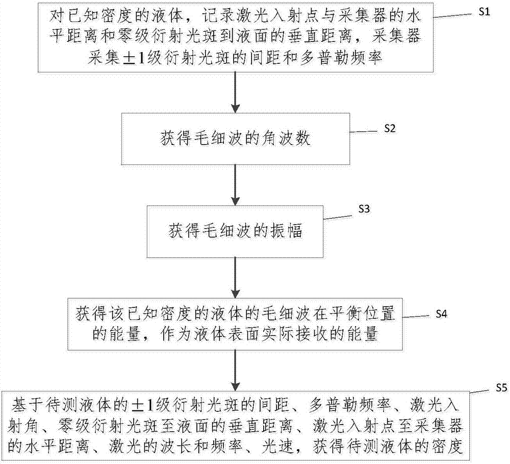
[0023] The specific implementation manners of the present invention will be further described in detail below in conjunction with the accompanying drawings and embodiments. The following examples are used to illustrate the present invention, but are not intended to limit the scope of the present invention.

[0024] In order to overcome the problems of non-real-time continuous measurement and contaminated liquid caused by the contact method used in the prior art to measure liquid density, the present invention provides a non-contact method for measuring liquid density that combines Doppler vibrometers and grating diffraction principles. system.

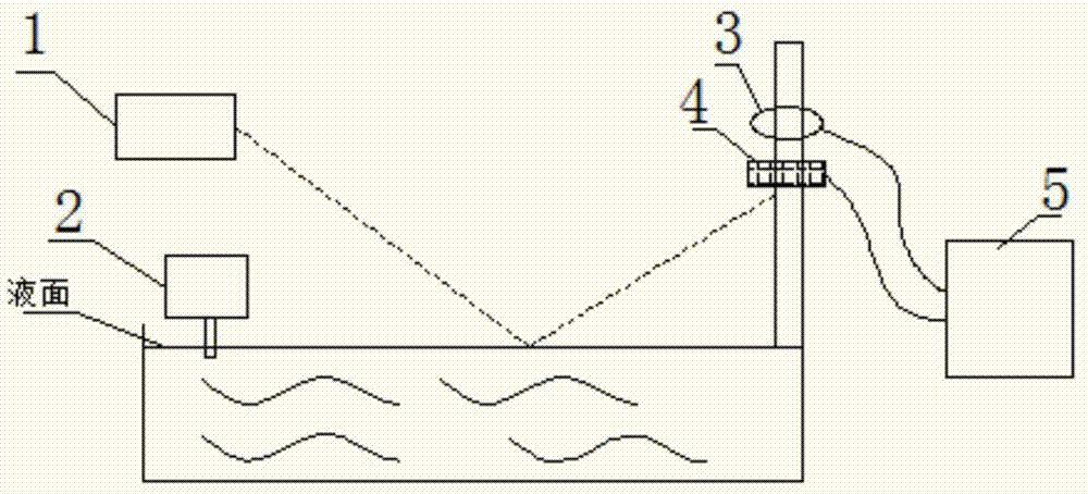
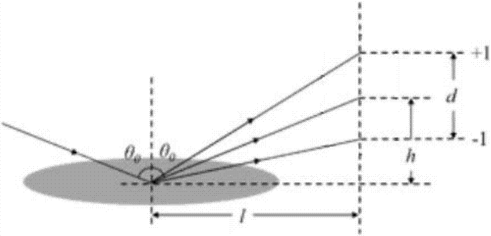
[0025] figure 1 A schematic structural diagram of a system for measuring liquid density according to an embodiment of the present invention is shown, by figure 1 It can be seen that this system includes:

[0026] The laser generator 1 is used to emit laser light of a certain wavelength to the surface of the liquid at a certain angle...


PUM


Abstract

The invention provides a system, method and application for detecting liquid density. The system comprises a laser generator, a capillary wave exciter, a collector, a geometrical parameter collector and a data processing device, wherein the laser generator is used for jetting a laser light in a certain wavelength to a liquid surface at a certain angle; the capillary wave exciter is used for generating a capillary wave on the liquid surface; the collector is used for collecting Doppler frequency and an interval of + / - level diffraction spot corresponding to the present liquid; the geometrical parameter collector is used for collecting the wavelength of the laser light, the frequency of the laser light, the incidence angle of the laser light, the frequency of the capillary wave exciter, a vertical distance from the zero level diffraction spot to the liquid surface and a horizontal distance from the incidence point of the laser light to the collector; and the data processing device is used for receiving the data collected by the collector and the geometrical parameter collector and calculating the liquid density. On the basis of a Doppler measuring principle and an optical grating diffraction principle, the system can achieve the effect of non-contact detection for liquid density, can realize convenient and quick real-time detection, is high in operation efficiency, can promote the detection efficiency and has continuous detection capacity.

Description

technical field [0001] The present invention relates to liquid density measurement technology, more specifically, to a system, method and application for detecting liquid density. Background technique [0002] The liquid surface wave can reflect the properties of the liquid, such as surface tension coefficient, viscosity coefficient, etc. On the basis of combining other parameters, the density of the solution can be measured indirectly. Among them, there are many methods for measuring the surface tension of liquids, most of which belong to the contact method or static Methods, such as pull-off method, titration method, capillary method, maximum bubble pressure method, etc., are commonly used. The disadvantage of these methods is that they cannot be measured continuously in real time, and they will pollute the liquid. [0003] The blister manure process is used to regularly remove the manure and urine in the livestock house, reduce the labor input in the manure cleaning proce...

Claims


Application Information

Patent Timeline
IPC IPC(8): G01N9/24
CPCG01N9/24
Inventor 陈一飞范立岩尹鸿苇王聃张向南李丹
Owner CHINA AGRI UNIV
Why Eureka
Try Eureka