

Transformer substation fiber perimeter security monitoring system
A fiber optic perimeter security and monitoring system technology, applied in anti-theft alarms, anti-theft alarm mechanical activation, alarms that rely on broken/disturbed straightened ropes/metal wires, etc., can solve the problem of not being able to determine dangers in a timely and accurate manner Location, false alarm rate, false alarm rate increase, difficult to adapt to security and other issues, to achieve the effect of easy operation and management, enhanced positioning accuracy, and low loss
- Summary
- Abstract
- Description
- Claims
- Application Information
AI Technical Summary
Problems solved by technology
Method used
Image

Examples
Embodiment 1
[0025] Embodiment 1: Installation method of vibration sensing optical cable hanging on the net (installed on the fence)
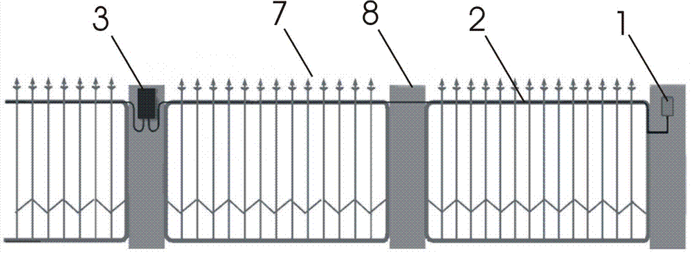
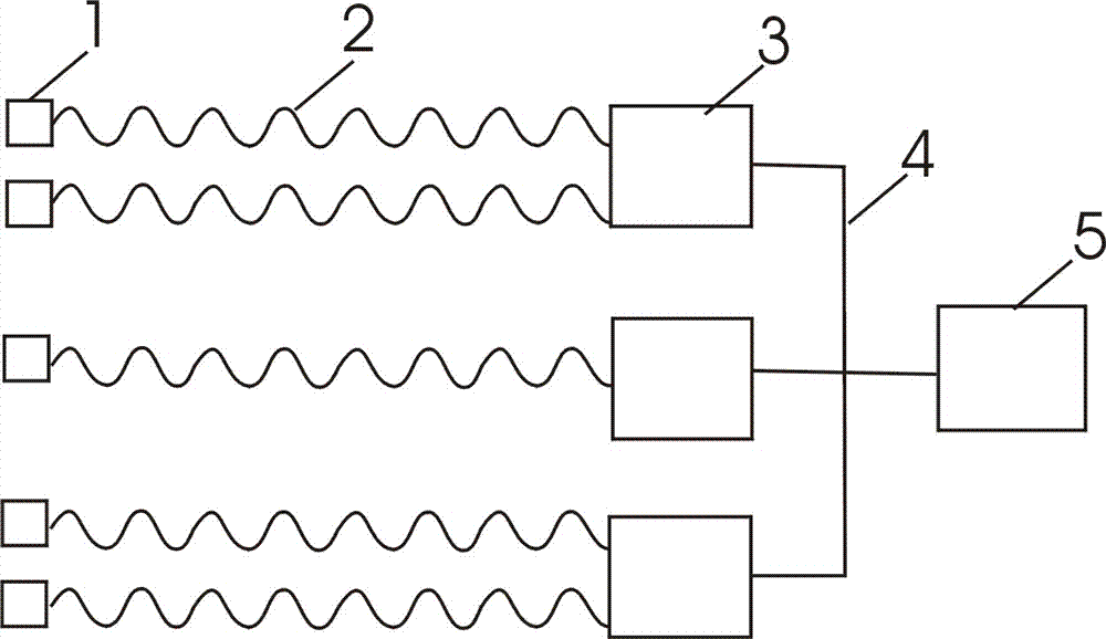
[0026] The vibration sensing optical cable 2 adopts the distributed vibration detection sensing optical cable of the patent No. 2011201346653, and is laid on the fence (see attached image 3 ), using linear laying: the vibration sensing optical cable 2 is laid at a position about 1.5 meters above the ground, and the vibration sensing optical cable 2 is tightly bound to the fence 7, and is bound once every 50 cm with a stainless steel cable tie. It is advisable that the optical cable is not deformed; the terminal unit 1 and the alarm monitoring unit 3 are respectively fixed on the pillar 8 of the fence, and a separate defense zone uses an alarm monitoring unit (collector) for itself, and it is believed that the defense zone shares a collector.
[0027] In addition to the above-mentioned linear laying, the vibration sensing optical cable can also be laid in p...
Embodiment 2
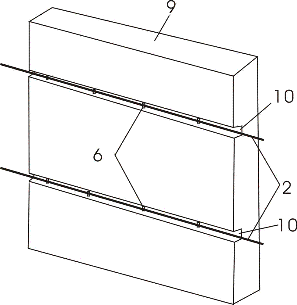
[0039] Embodiment 2: Laying method of anti-chisel wall vibration sensing optical cable
[0040] The vibration sensing optical cable is laid along the wall, and each vibration sensing optical cable can prevent the wall body of 50cm up and down. On the wall body 9, a groove 10 is dug at a position of 1 meter and 3 meters above the ground, and the vibration sensing optical cable 2. Lay it in the groove 10, and fix the vibration sensing optical cable 2 on the wall with clips 6 every 50cm to prevent people from digging into the wall.
[0041] The vibrating optical cable system is a "tangible" alarm system, which really gives people a sense of deterrence, increases the psychological pressure of intruders, and can prevent and warn potential intrusion behaviors, so that the alarm system and the vigilance The system is organically combined to achieve the purpose of focusing on prevention and combining prevention and alarm. Used in the field of perimeter security, it can deter in advan...
PUM
 Abstract
Description
Claims
Application Information