Cold cathode supporting use of magnetron and production method for cold cathode head

A production method and cold cathode technology, applied in the field of microwave generation sources, can solve the problems of inability to provide secondary electron emission, unsuitable application of magnetron, long start-up time, etc., and achieve strong electron emission ability and anti-electron bombardment ability , Overcoming the effect of long warm-up time and stable launch speed

Inactive Publication Date: 2017-08-18
UNIV OF ELECTRONICS SCI & TECH OF CHINA
View PDF6 Cites 3 Cited by
  • Summary
  • Abstract
  • Description
  • Claims
  • Application Information

AI Technical Summary

Problems solved by technology

In the article "Thin Film Field Emission Cold Cathode" (see "Optoelectronics Technology" 1989, No. 04, author: Chen Lifang et al.), a microelectronic source using a three-sandwich structure cold cathode is disclosed. The microelectronic source has room temperature work, no cathode power consumption, no warm-up delay, etc., but it uses a planar emission structure, needs to add a gate, and the emission current is small, and cannot provide secondary electron emission
However, the carbon nanotube cold cathode disclosed in the patent document with the application number CN201510675065.0 and the invention titled "A Microwave-modulated Cold Cathode Micro-Array Radiation Source and Its Realization Method" also adopts a planar emission structure and cannot provide two Sub-electron emission, not suitable for use in magnetrons
[0004] In the patent document with the application number 2016101968038 and titled "Production Method of Magnetron Using Combined Cold Cathode Head and Cold Cathode Body", the applicant discloses an upper and lower shielding cap made of graphene and carbon nanotubes. A cold cathode body made by mixing one or more of zinc oxide nanowires with metal powder, and a tungsten or tungsten alloy elect

Method used


Image

  • Cold cathode supporting use of magnetron and production method for cold cathode head
  • Cold cathode supporting use of magnetron and production method for cold cathode head
  • Cold cathode supporting use of magnetron and production method for cold cathode head

Examples


Embodiment 1

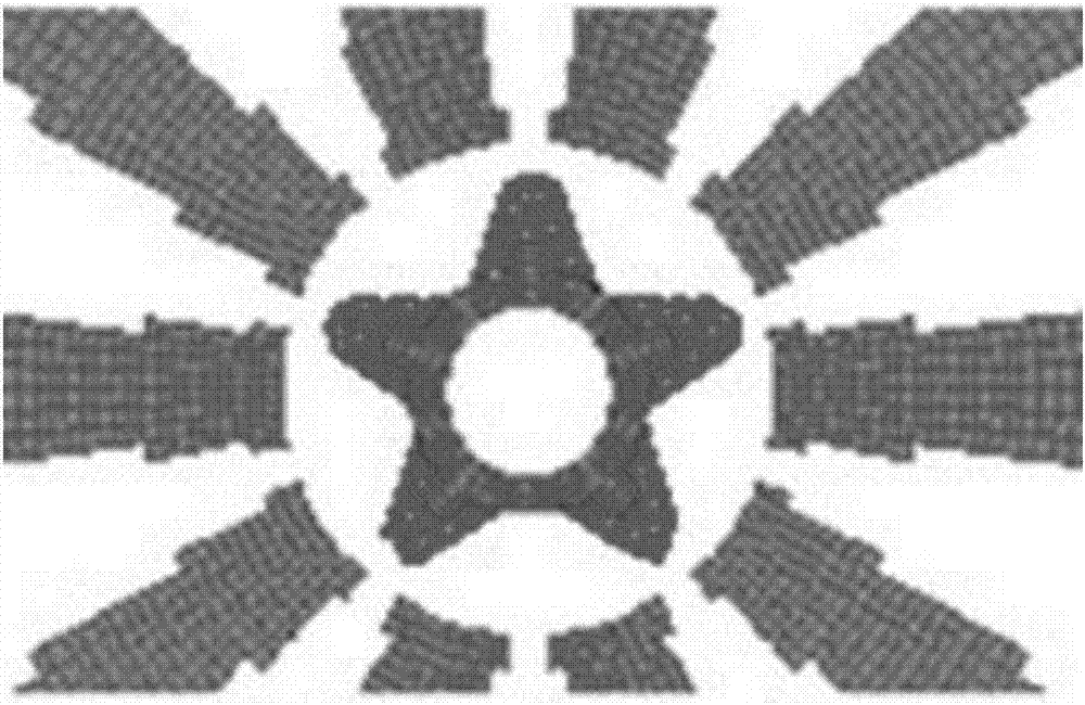
[0023] Embodiment 1: account for 10wt% with producing graphene, the cold cathode head of band five trapezoidal teeth is example:

[0024]Step 1. Material preparation: Weigh 5g of graphene powder; then prepare 15g each of electrolytic Cu powder, electrolytic Al powder and electrolytic Mg powder with a particle size of less than 30 μm to make metal mixed powder for use;

[0025] Step 2. Ball milling and mixing: the graphene powder and metal mixed powder described in step 1 are placed in a ball milling tank, and the ball milling is mixed for 120 minutes to obtain the mixed powder; Monomer ball milling tank with an inner diameter of Φ35mm, a height of 60mm, and a rotating speed of 1425 rpm. There are 5 steel balls with a diameter of Φ5mm and 15 steel balls with a diameter of Φ8mm for grinding balls (the ball-to-material ratio is 1:1.42);

[0026] Step 3. Compaction: Put the mixed powder obtained in Step 2 into the mold, and press it directly under a pressure of 60MPa to form a hei...

Embodiment 2

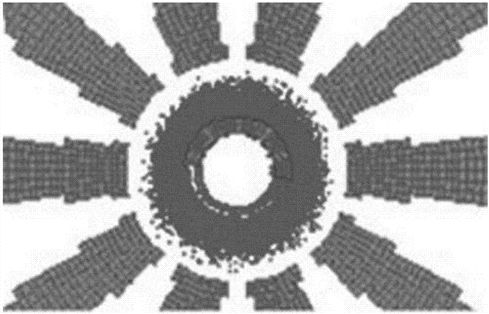
[0031] Embodiment 2: account for 10wt% with the production graphene, the cold cathode head that the tooth shape is fan-shaped teeth is example:

[0032] Steps 1 and 2 are all the same as in Example 1;

[0033] Step 3. Compaction: put the mixed powder obtained in step 2 into a mold, and press it under a pressure of 50MPa to form a cylindrical body with a height of 9.5mm and a diameter of Φ8.5mm;

[0034] Step 4. Molding: put the cold cathode head compact formed in step 3 in a vacuum furnace, sinter at a temperature of 630±10°C and an Ar gas environment for 100 minutes, and then cool with the furnace to obtain a cylindrical sintered body; then On the cylindrical surface of the cylindrical sintered body, mill a rectangular through groove with the height of the sintered body at intervals of 72° in the axial direction, with a groove width of 1mm and a depth of 0.5mm to obtain a cold cathode head with five fan-shaped teeth .

[0035] Gained cold cathode heads are assembled into co...

Embodiment 3

[0036] Embodiment 3: take the production of graphene and carbon nanotubes each accounting for 5wt%, and the tooth shape is an example of a cold cathode head with fan-shaped teeth:

[0037] Step 1. Preparation of materials: Weigh graphene powder and 2.5g each of carbon nanotubes with a length of 500nm-5μm; then mix 15g each of electrolytic Cu powder, electrolytic Al powder and electrolytic Mg powder with a particle size of less than 30 μm. powder, set aside;

[0038] Step 2. Ball milling, Step 3. Compacting, and Step 4. Forming are all the same as in Example 2, and a cold cathode head with five fan-shaped teeth is obtained.

[0039] Gained cold cathode heads are assembled into cold cathodes in the same manner as in Example 1, and put into a vacuum chamber, and the vacuum degree is 1 × 10 -4 The test is carried out under the conditions of Pa and voltage of 5000V, and the emission current is 102mA.


PUM

PropertyMeasurementUnit
Particle sizeaaaaaaaaaa

Abstract

The invention provides a cold cathode supporting use of a magnetron and a production method for the cold cathode head. The cold cathode includes an upper shielding cap and a lower shielding cap, and a power connection rod and the integral post tooth-shaped cold cathode head. The method includes preparing material, ball grinding and mixing, blank pressing and molding. According to the invention, since grapheme or/and carbon nanometer tubes, zinc oxide nanometer wires are adopted to mix with metal power for blank pressing, sintering and processing so as to prepare the integral post tooth-shaped cold cathode head, after primary electrons are emitted by the cold cathode head under the effect of high voltage, back bombardment of the primary electrons excites gear teeth to emit secondary electrons, and stable electron emission is formed in the repeat process and stable output can be achieved within only 40 nanoseconds. Therefore, compared with a thermionic cathode, advantages such as electron emitting capability of the thermionic cathode, high electron bombardment resistance and the like are kept and shortcomings of long pre-heating time, low starting rate and short service lifetime and the like are overcome. Compared with a cold cathode in background art, the cold cathode provided by the invention has characteristics of simple structure, high electron emitting capability, high electron bombardment resistance, pure frequency spectrum output, high and stable emitting speed and the like.

Description

technical field [0001] The invention belongs to the technical field of microwave device production, in particular to a production method of a cold cathode and a cold cathode head matched with a magnetron. The magnetron adopting the cold cathode emission system of the invention has better field emission capability and fast The function of exciting the magnetron is especially suitable as a microwave source for microwave application equipment including domestic microwave ovens. Background technique [0002] Magnetron is one of the most widely used electronic vacuum tubes. Because of its advantages of high efficiency, high power, small size, low working voltage and convenient use, it is a high power source in microwave technology. Magnetrons are generally used in various microwave heating devices. After years of research and exploration, the design and production of magnetrons are becoming more and more mature. Mass production can further reduce the cost of the magnetron and gr...

Claims


Application Information

Patent Timeline
IPC IPC(8): H01J23/05H01J9/02H01J9/12
CPCH01J9/025H01J9/125H01J23/05
Inventor 柳建龙乐晨光曾葆青吴喆
Owner UNIV OF ELECTRONICS SCI & TECH OF CHINA
Why Eureka
Try Eureka