
Light emitting diode (LED), printed circuit board (PCB), plug hole metal-based copper coating plate and fabrication method of plug hole metal-based copper coating plate

A technology of metal substrate and manufacturing method, which is applied in the manufacture of printed circuits, printed circuits connected with non-printed electrical components, printed circuits, etc. and other problems, to achieve the effect of having both insulation performance and heat dissipation performance, improving production efficiency, and combining firmness

Inactive Publication Date: 2017-08-18
广州市谷建杰电子有限公司
View PDF3 Cites 6 Cited by
  • Summary
  • Abstract
  • Description
  • Claims
  • Application Information

AI Technical Summary

Problems solved by technology

Obviously, another insulating layer causes waste of materials, which further limits the improvement of heat dissipation performance, and the step of manually placing the insulating layer sheet leads to an increase in labor costs and production consumable costs, as well as a reduction in production efficiency

Method used


Image

  • Light emitting diode (LED), printed circuit board (PCB), plug hole metal-based copper coating plate and fabrication method of plug hole metal-based copper coating plate
  • Light emitting diode (LED), printed circuit board (PCB), plug hole metal-based copper coating plate and fabrication method of plug hole metal-based copper coating plate
  • Light emitting diode (LED), printed circuit board (PCB), plug hole metal-based copper coating plate and fabrication method of plug hole metal-based copper coating plate

Examples


Embodiment Construction

[0026] The plugged metal-based copper-clad laminate provided by the present invention and its manufacturing method will be further described below in conjunction with the accompanying drawings. It should be pointed out that the technical solution and design principle of the present invention will be described in detail below with an optimized technical solution.

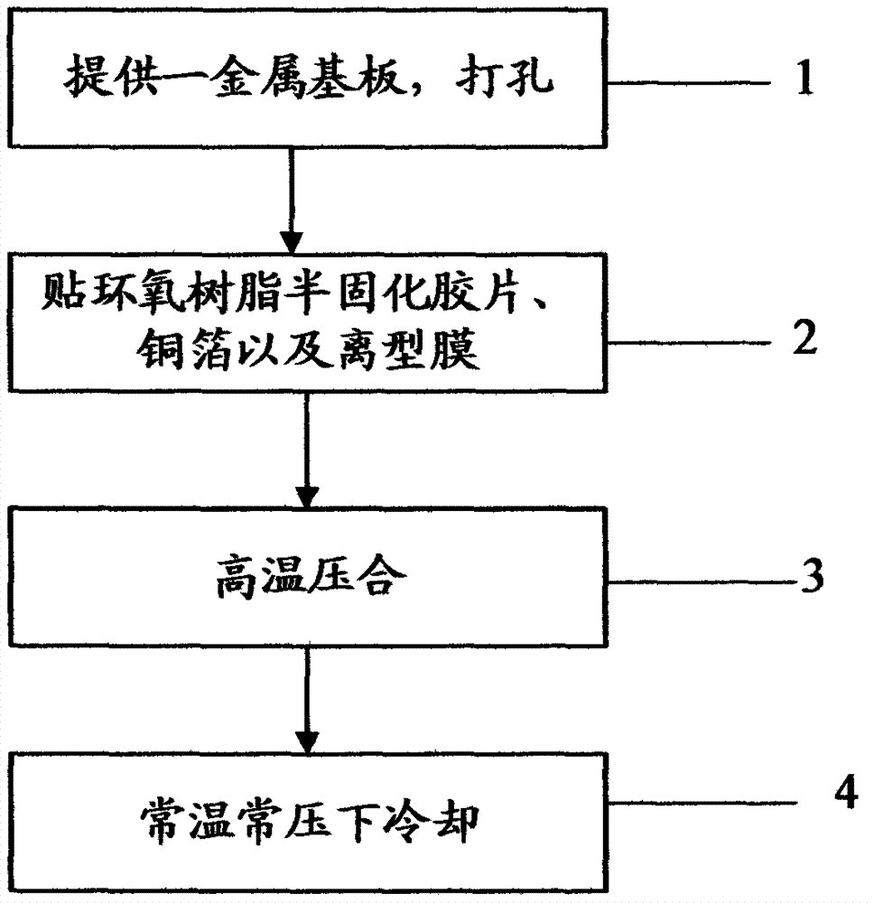
[0027] Such as figure 1 As shown, the method for manufacturing a plugged metal-based copper clad laminate provided by a preferred embodiment of the present invention includes: step 1, providing a metal substrate, drilling holes; step 2, pasting epoxy prepreg, copper foil and release film ; Step 3, high-temperature pressing; and Step 4, cooling under normal temperature and pressure to obtain a metal-based copper-clad laminate with plugged holes.

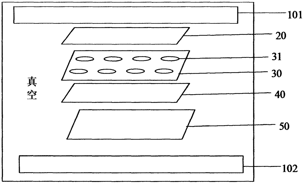
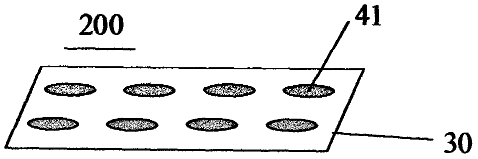
[0028] combine figure 2 As shown, in step 1, drilling refers to forming a predetermined number and layout of through holes 31 on the metal substrate 30 . In this embodime...


PUM

PropertyMeasurementUnit
thermal conductivityaaaaaaaaaa

Abstract

The invention relates to a plug hole metal-based copper coating plate and a fabrication method thereof. The fabrication method of the plug hole metal-based copper coating plate comprises the steps of 1, providing a metal substrate, and punching the metal substrate; 2, pasting an epoxy resin semi-cured film, a copper foil and a release film; 3, performing high-temperature lamination; and 4, performing cooling under normal temperature and normal pressure to obtain the plug hole metal-based copper coating plate. A certain number of through holes are formed in the plug hole metal-based copper coating plate and the metal substrate thereof according to a certain layout, the through holes are filled with insulation voltage-resistant thermal conduction sheets, and the thicknesses of the insulation voltage-resistant thermal conduction sheets can approximate to the thickness of the metal substrate; due to high-temperature lamination formation in one time, the insulation voltage-resistant thermal conduction sheets and the metal substrate are firmly combined, the insulation voltage-resistant thermal conduction sheets have relatively large thicknesses, and an alternating current is prevented from being instantaneously broken down by high voltage; and the metal substrate also has favorable heat dissipation performance, thus, the plug hole metal-based copper coating plate is compatible with insulation performance and heat dissipation performance, and is particularly and suitably applied to an LED integrated circuit board.

Description

technical field [0001] The invention relates to a printed circuit board and a manufacturing method thereof, in particular to a plug hole metal-based copper-clad board and a manufacturing method thereof. Background technique [0002] With the development of electronic information technology, electronic products are developing in the direction of light weight, miniaturization and high speed, which puts forward higher requirements for printed circuit boards. In the era of high-density connection technology, the line width and line spacing will inevitably develop towards smaller and denser. In order to adapt to this development trend, printed circuit board designers and manufacturers are also constantly updating design concepts and manufacturing methods. The process of resin plugging is also a technical method invented by people to reduce the design size of printed boards and cooperate with assembly components. Its bold design concept and scalable production have indeed played...

Claims


Application Information

Patent Timeline
Patent Type & Authority Applications(China)
IPC IPC(8): H05K1/02H05K1/11H05K3/40H05K1/18
CPCH05K1/0206H05K1/115H05K1/181H05K3/4038H05K2201/0959H05K2201/10106
Inventor 谷彬
Owner 广州市谷建杰电子有限公司
Learn More