Welding manufacturing method of electron beam sleeved with large diameter T-shaped ring

A technology of electron beam welding and manufacturing method, which is applied to the field of electron beam welding manufacturing of large-diameter T-rings, which can solve the problems of difficulty in accurately guaranteeing dimensional accuracy, structural instability and damage, large welding deformation, etc.

Inactive Publication Date: 2017-08-22
725TH RES INST OF CHINA SHIPBUILDING INDAL CORP
View PDF6 Cites 5 Cited by
  • Summary
  • Abstract
  • Description
  • Claims
  • Application Information

AI Technical Summary

Problems solved by technology

[0003] Aiming at the welding of large-thickness inner-set T-shaped bar in the above-mentioned prior art, traditional welding methods such as metal argon arc welding or tungsten argon arc welding are used for fillet weld welding, the existing welding efficiency is low, welding deformation is large, and the size afte

Method used


Image

  • Welding manufacturing method of electron beam sleeved with large diameter T-shaped ring
  • Welding manufacturing method of electron beam sleeved with large diameter T-shaped ring
  • Welding manufacturing method of electron beam sleeved with large diameter T-shaped ring

Examples


Embodiment 1

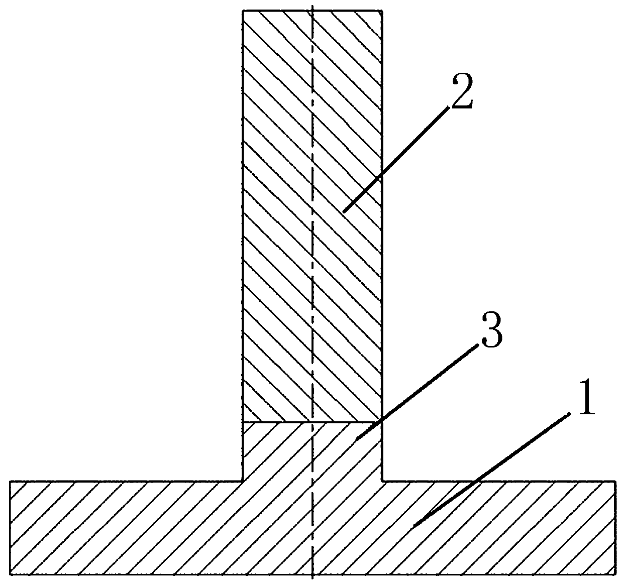
[0024] For a TC4 titanium alloy T-ring inner suit with a panel inner diameter of 1200mm, a width of 30mm, a thickness of 10mm, a rib height of 80mm, and a thickness of 10mm, the designed boss height is 2mm. Adjust the relative position of the panel and the rib, the assembly gap between the panel and the rib is less than 0.3mm, the axial misalignment is less than 0.2mm, fix it with the pressure plate and the clamping device; the vertical tolerance of the rib and the panel meets the requirements, less than 0.5mm, The outer diameter meets the requirements; the panel and the rib are spot welded, and the welding method is spot welding by manual argon tungsten arc welding. 0.2mm; Fix the assembled workpiece on the welding turntable and align it, put it into the vacuum chamber to evacuate, so that the vacuum degree reaches 5×10 -3 Weld the workpiece when it is below MPa; after vacuuming, start the electron beam welding machine, adjust the welding angle of the electron gun, so that th...

Embodiment 2

[0026] For the 40Cr steel T-ring inner suit with a panel inner diameter of 2800mm, a width of 35mm, a thickness of 20mm, a rib height of 75mm, and a thickness of 15mm, the designed boss height is 4mm. Before assembly, the residual magnetic content of the workpiece to be welded needs to be checked and demagnetized. Make the residual magnetic quantity≤1×10 -4 T; After the panel and the rib are assembled, put them on the welding platform and fix them, adjust the relative position of the panel and the rib. The device is fixed; the verticality tolerance of ribs and panels meets the requirements, less than 0.5mm, and the outer diameter meets the requirements; the panel and ribs are spot welded, and the welding method is spot welding by manual tungsten argon arc welding, and the spot welding points are evenly distributed At 8 positions of the weld to be welded, the assembly gap is uniform and stable, less than 0.2mm; fix the assembled workpiece on the welding turntable and align it, ...


PUM


Abstract

The invention relates to a welding manufacturing method of an electron beam sleeved with a large diameter T-shaped ring. The welding manufacturing method can replace currently-adopted sleeving in a large diameter T-shaped ring prepared by traditional welding methods such as metal argon arc welding or argon tungsten arc welding. A boss with the same width with a rib plate is machined on a face plate, it is guaranteed that an assembling gap between the face plate and the rib plate are welded through the electron beam, and the problems that in the prior art, when welding of T profile sleeved with the large thickness ring adopts the traditional welding methods such as metal argon arc welding or argon tungsten arc welding to conduct fillet seam welding, the welding efficiency is low, welding deformation is large, welding dimension precision is difficult to accurately guarantee, the stress concentration condition of a fillet seam is serious, and thus structure instability damage is prone to occurring are effectively solved.

Description

technical field [0001] The invention relates to the technical field of metal material welding, in particular to a large-diameter T-ring inner sleeve electron beam welding manufacturing method. Background technique [0002] The interior of the large-scale external pressure-bearing structure is designed and processed with annular ribs to increase the rigidity, usually T-shaped, so it is called T-ring inner sleeve. It mainly adopts a welded structure, and the weld seam connects the panel and the rib plate to form a whole, so as to achieve the purpose of improving the structural strength and ensuring the structural stability. There are a large number of inner rings in large structures, the welding process is complicated, and the welding accuracy is difficult to guarantee. Therefore, the welding of inner rings has always been a key component in the manufacturing process of large external pressure-bearing structures, which directly affects the production cycle and product quality ...

Claims


Application Information

Patent Timeline
IPC IPC(8): B23K15/04
CPCB23K15/04
Inventor 高福洋高奇张明辉张毅刘志颖蒋鹏
Owner 725TH RES INST OF CHINA SHIPBUILDING INDAL CORP
Why Eureka
Try Eureka