Spinning target time-varying three-dimensional imaging method based on linear frequency modulation stepped signal

A linear frequency modulation stepping, three-dimensional imaging technology, applied in the direction of radio wave reflection/re-radiation, radio wave measurement system, utilization of re-radiation, etc., can solve the problems of complex system implementation, radar synchronization, occlusion effect, etc., and achieve system sensitivity sex high effect

Active Publication Date: 2017-08-22
AIR FORCE UNIV PLA
View PDF4 Cites 12 Cited by
  • Summary
  • Abstract
  • Description
  • Claims
  • Application Information

AI Technical Summary

Problems solved by technology

However, when the above methods obtain the real 3D imaging results and 3D micro-motion features of the target, they all need to jointly process the echoes of multiple radars located at different angles of view. Anisotropy, occlusion effects and other issues, and the system implementation is more complicated
In order to solve the above problems in the 3D imaging method of space targets, an interferometric 3D imaging method in narrowband radar was proposed (see Chen Yongan's "Multi-antenna Interferometric Processing of Narrowband Radar Space Rotating Target 3D Imaging", published in "Journal of Air Force Engineering University (Natural Science Edition), 2016, No. 17), through the interferometric calibration of the echoes of different scattering points in the time-frequency domain, but due to the low range resolution of narrowband radar, it is impossible to obtain the range direction of each scattering point. the real coordinates of

Method used


Image

  • Spinning target time-varying three-dimensional imaging method based on linear frequency modulation stepped signal
  • Spinning target time-varying three-dimensional imaging method based on linear frequency modulation stepped signal
  • Spinning target time-varying three-dimensional imaging method based on linear frequency modulation stepped signal

Examples


example

[0071] Example: Time-varying 3D imaging simulation experiment

[0072] Simulation experiment: In order to verify the effectiveness of the algorithm proposed in the present invention, we carried out the following computer simulation. The radar emits a chirp signal. The parameter settings required for data simulation are shown in Table 1.

[0073] Table 1 Simulation parameter settings

[0074]

[0075] Simulation 1: In order to verify the effectiveness of the algorithm, the following simulation experiment is now carried out. Suppose there are three scattering points on the target, the rotation frequency is 2.5Hz, the rotation radius is (0.95, 1.52, 1.99) m, and the scattering coefficient is 1.

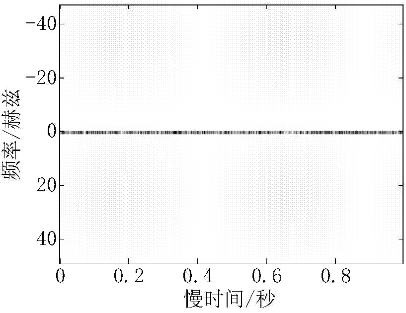
[0076] Step 1: Delineate and tune the echo signal, perform one-dimensional range imaging, and use the coarse-resolution range image to synthesize the fine-resolution range image. The obtained coarse-resolution range image and high-resolution range image sequence are shown in Fig. 3...


PUM


Abstract

The invention provides a spinning target time-varying three-dimensional imaging method based on a linear frequency modulation stepped signal. The spinning target time-varying three-dimensional imaging method comprises the steps of: step 1, subjecting data echo to ''Dechirp'' and translational motion compensation processing, carrying out range-slow time imaging, processing an obtained coarse-resolution range image, and synthesizing to obtain a fine-resolution range image; step 2, extracting echo curve parameters of scattering points in the fine-resolution range image through Hough transform, further acquiring echo trajectories of the scattering points; step 3, and performing interference processing on three antenna echoes along the trajectory directions to obtain two-dimensional coordinates, further performs range walk compensation on range direction positions represented by the trajectories to obtain three-dimensional coordinates, and finally acquiring a three-dimensional image of the scattering points through integrating the obtained three-dimensional coordinates. According to the spinning target time-varying three-dimensional imaging method, the linear frequency modulation stepped signal has a narrow instant bandwidth and has a large synthetic bandwidth at the same time, and the spinning target time-varying three-dimensional imaging method can be applied to a narrowband radar to improve the imaging quality and reduce the burden on a hardware system.

Description

technical field [0001] The invention relates to signal and information processing technology, in particular to a spin target time-varying three-dimensional imaging method based on a linear frequency modulation step signal. Background technique [0002] In recent years, with the rapid increase in the number of space objects such as space debris, satellites, and ballistic missiles, the space environment has become increasingly complex. Carrying out space object tracking, measurement, classification, and identification is crucial to ensuring my country's space security, promoting the development of national space technology, and space peace. Utilization is very important. [0003] As an important means of space surveillance, radar imaging technology plays a significant role in target classification and recognition. Since space targets mostly have various forms of micro-motion such as spin, precession, and rollover, each scattering point on the target will move across the distan...

Claims


Application Information

Patent Timeline
Patent Type & Authority Applications(China)
IPC IPC(8): G01S13/89G01S7/41
CPCG01S7/41G01S13/89
Inventor 张群孙玉雪罗迎孙莉李开明苏令华
Owner AIR FORCE UNIV PLA
Why Eureka
Try Eureka