Cleaning device for intermediate bulk container for liquid chemicals

A cleaning device and chemical technology, applied in the direction of chemical instruments and methods, cleaning hollow objects, cleaning methods and utensils, etc., can solve the problems of increased energy consumption, inconvenience, and increased amount of cleaning waste liquid in drying treatment, and achieve a reduction in tons Drum loading and unloading operations, improvement of processing efficiency, and reduction in usage

Active Publication Date: 2017-08-25
JIANGYIN JIANGHUA MICROELECTRONICS MATERIAL
View PDF9 Cites 5 Cited by
  • Summary
  • Abstract
  • Description
  • Claims
  • Application Information

AI Technical Summary

Problems solved by technology

Due to the large weight and volume of the tonnage, and due to the different contents, there will be some inconvenience in manual handling
CN105728414A A lift is used to switch between the cleaning station of the ton barrel and the initial station of feeding and discharging materials; the solvent in the ton barrel flows out through the liquid outlet valve at the bottom, which is not conducive to the maximum discharge of the liquid in the barrel, and will inevitably cause drying. increase in energy consumption; CN205393129U discloses an automatic cleaning system for totes, which is provided with a rotating nozzle and a return flow assembly for discharging waste liquid from totes for cleaning, but there is a small amount of waste liquid in the totes for actual cleaning operations. For example, waste acid, etc., if not pre-treated, will lead to a substantial increase in the amount of cleaning waste liquid, and in general increase the difficulty of cleaning waste liquid treatment
In addition, due to the difference in the contents of the totes, the open tote cleaning system is not suitable for totes whose contents are volatile acids; in addition, the cleaning system in the prior art has a low degree of automation, and the participation of operators is not conducive to guarantee Safety in the cleaning process

Method used


Image

  • Cleaning device for intermediate bulk container for liquid chemicals
  • Cleaning device for intermediate bulk container for liquid chemicals
  • Cleaning device for intermediate bulk container for liquid chemicals

Examples


Embodiment 1

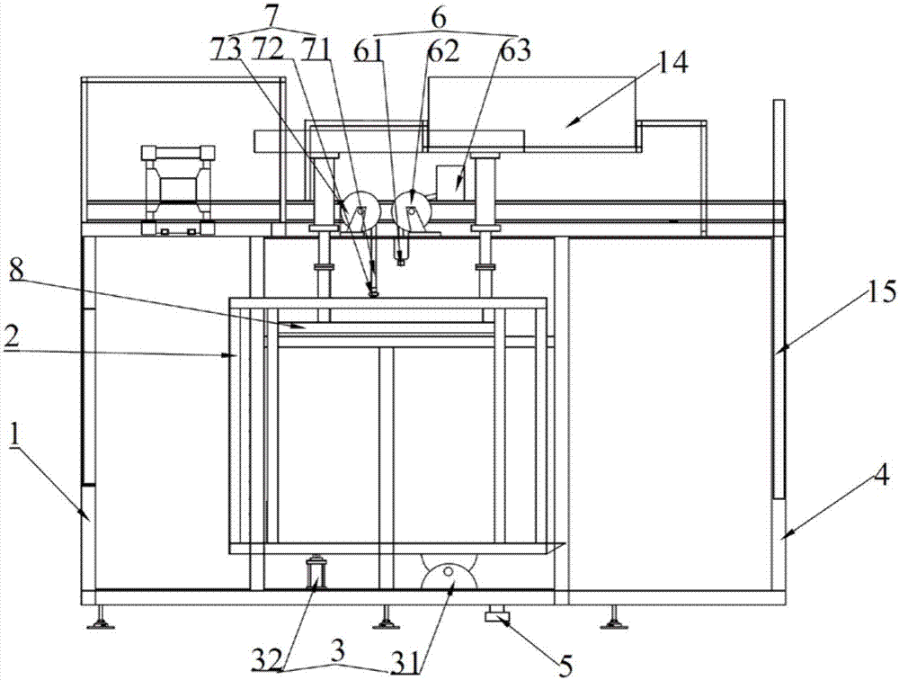
[0033] Such as figure 1 As shown, the liquid chemical ton barrel cleaning device in Example 1 includes a cleaning chamber 1, a barrel loading frame 2 and a turning mechanism 3. One side of the cleaning chamber 1 is provided with a ton barrel inlet and outlet 4, and the bottom end is provided with a cleaning waste liquid Outlet 5, the turning mechanism is used to drive the barrel frame 2 to turn over in the inner cavity of the cleaning chamber 1, and the cleaning chamber 1 is provided with a barrel pumping component 6 and a barrel inner wall cleaning component 7 matched with the barrel frame 2. The bucket frame is provided with a limit piece matched with the tote bucket.

[0034] In Embodiment 1, the overturning mechanism 3 is arranged below the barrel frame 2, and the barrel frame 2 is connected to the hinge 31 below, and an oil cylinder 32 is arranged between the bottom of the barrel frame 2 and the bottom surface of the cleaning chamber (for driving the barrel The frame rot...

Embodiment 2

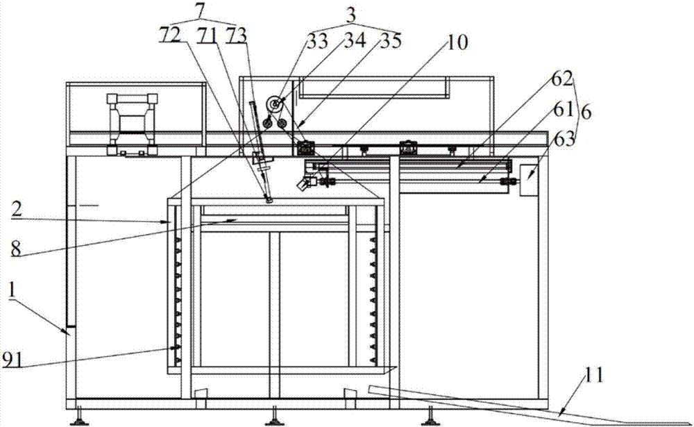
[0041] Such as figure 2 As shown, the difference between embodiment 2 and embodiment 1 is that the turning mechanism 3 includes a transmission assembly and a drive motor 34, the transmission assembly is a pulley 35 pulley 33 mechanism, and at least three Click to connect. Concrete, among the embodiment 2, PVC traction rope 35 is connected with the top four corners of bucket frame 2.

[0042] The suction pipe retractable mechanism 62 and the cleaning liquid pipe lifting mechanism 73 are all rodless cylinders.

[0043] The cleaning chamber of embodiment 2 is also provided with a barrel outer wall cleaning assembly 9, which is an outer wall spray head 91 fixedly connected to the vertical pillar of the barrel carrying frame.

[0044] The liquid suction pipe is a corrugated pipe, and the liquid suction assembly in the barrel also includes a guide ring 10, which is sleeved on the periphery of the liquid suction pipe 61, and is fixedly connected between the guide ring 10 and the l...

Embodiment 3

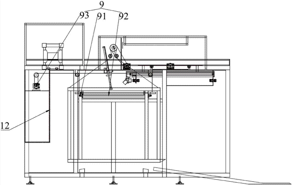
[0048] Such as Figure 3-5 As shown, the difference between embodiment 3 and embodiment 2 is that the barrel outer wall cleaning assembly includes an outer wall nozzle 91, a cage 92 and a cage lifting mechanism 93, and the outer wall nozzle 91 is fixedly arranged on the inner surface of the cage 92, and the cage 92 uses It is sleeved on the outer periphery of the tonnage and has a spray gap with the outer surface of the tonneau. Cage lifting mechanism 93 adopts the structure of PVC traction rope and motor-driven sheave equally.

[0049] A corrosion-resistant interlayer 12 is provided on the inner surface of the cleaning chamber 1 and the outer surface of the bucket frame 2 .

[0050] Three pumping units are arranged in the liquid pumping assembly in the barrel, and each liquid pumping unit includes a liquid pumping tube 61 , a liquid pumping tube retractable mechanism 62 and a liquid pumping pump 63 . The above three pumping units are respectively used for pumping hydrofluor...


PUM


Abstract

The invention discloses a cleaning device for an intermediate bulk container for liquid chemicals. The cleaning device for the intermediate bulk container for the liquid chemicals comprises a cleaning chamber, an intermediate bulk container carrying frame and an overturning mechanism, wherein an intermediate bulk container inlet-outlet is formed in one side of the cleaning chamber; a cleaning waste liquid outlet is formed in the bottom end of the cleaning chamber; the overturning mechanism is used for driving the intermediate bulk container carrying frame to overturn in the inner cavity of the cleaning chamber; a limit element matched with the intermediate bulk container is arranged on the intermediate bulk container carrying frame; and an inner liquid pumping assembly for the intermediate bulk container and an inner wall cleaning assembly for the intermediate bulk container are arranged at the top end of the intermediate bulk container carrying frame. The cleaning device for the intermediate bulk container for the liquid chemicals is simple in structure; the structure is capable of ensuring a clean environment for cleaning operation through the arrangement of the cleaning chamber and the intermediate bulk container carrying frame capable of overturning; and the intermediate bulk container carrying frame drives the intermediate bulk container to overturn, so that a residual liquid and a cleaning liquid in the intermediate bulk container can be thoroughly pumped away, and the usage amount of the cleaning liquid and the treatment amount of a cleaning waste liquid are reduced.

Description

technical field [0001] The invention relates to cleaning equipment for chemical containers, in particular to a liquid chemical ton barrel cleaning device. Background technique [0002] Ton barrels of liquid chemicals often need to be reused in actual use. In order to avoid introducing new impurity ions into the filled chemicals, the ton barrels need to be cleaned and dried before filling. Due to the large weight and volume of the tonnage, and due to the different contents, there will be some inconvenience in manual handling. CN105728414A A lift is used to switch between the cleaning station of the ton barrel and the initial station of feeding and discharging materials; the solvent in the ton barrel flows out through the liquid outlet valve at the bottom, which is not conducive to the maximum discharge of the liquid in the barrel, and will inevitably cause drying treatment increase in energy consumption; CN205393129U discloses an automatic cleaning system for totes, which is...

Claims


Application Information

Patent Timeline
Patent Type & Authority Applications(China)
IPC IPC(8): B08B9/20B08B9/30
CPCB08B9/20B08B9/30
Inventor 朱永刚殷福华丁磊
Owner JIANGYIN JIANGHUA MICROELECTRONICS MATERIAL
Why Eureka
Try Eureka