Welding device and method for assembling optical fiber gyro

A fiber optic gyroscope and welding device technology, applied in laser welding equipment, welding equipment, metal processing equipment and other directions, can solve the problems of incomplete electromagnetic shielding effect, inaccurate output of fiber optic gyroscope, etc., to achieve magnetic shielding effect, The effect of preventing the deformation of structural parts and the simple and compact structure of the device

Active Publication Date: 2017-08-25
BEIJING AEROSPACE TIMES OPTICAL ELECTRONICS TECH
View PDF5 Cites 5 Cited by
  • Summary
  • Abstract
  • Description
  • Claims
  • Application Information

AI Technical Summary

Problems solved by technology

The existing fiber optic gyroscope components do not use welding devices, resulting in inaccurate output of fiber optic gyroscopes, and complete electromagnetic shielding effects cannot be achieved

Method used


Image

  • Welding device and method for assembling optical fiber gyro
  • Welding device and method for assembling optical fiber gyro
  • Welding device and method for assembling optical fiber gyro

Examples


Embodiment Construction

[0042] The present invention will be further described in detail below in conjunction with the accompanying drawings.

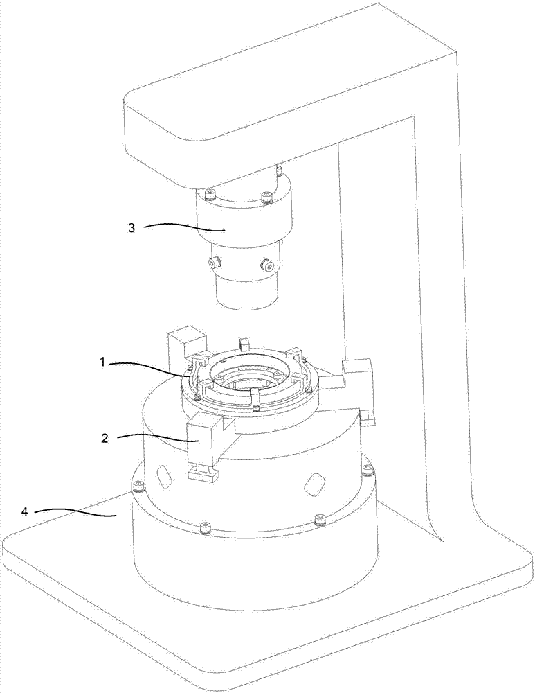
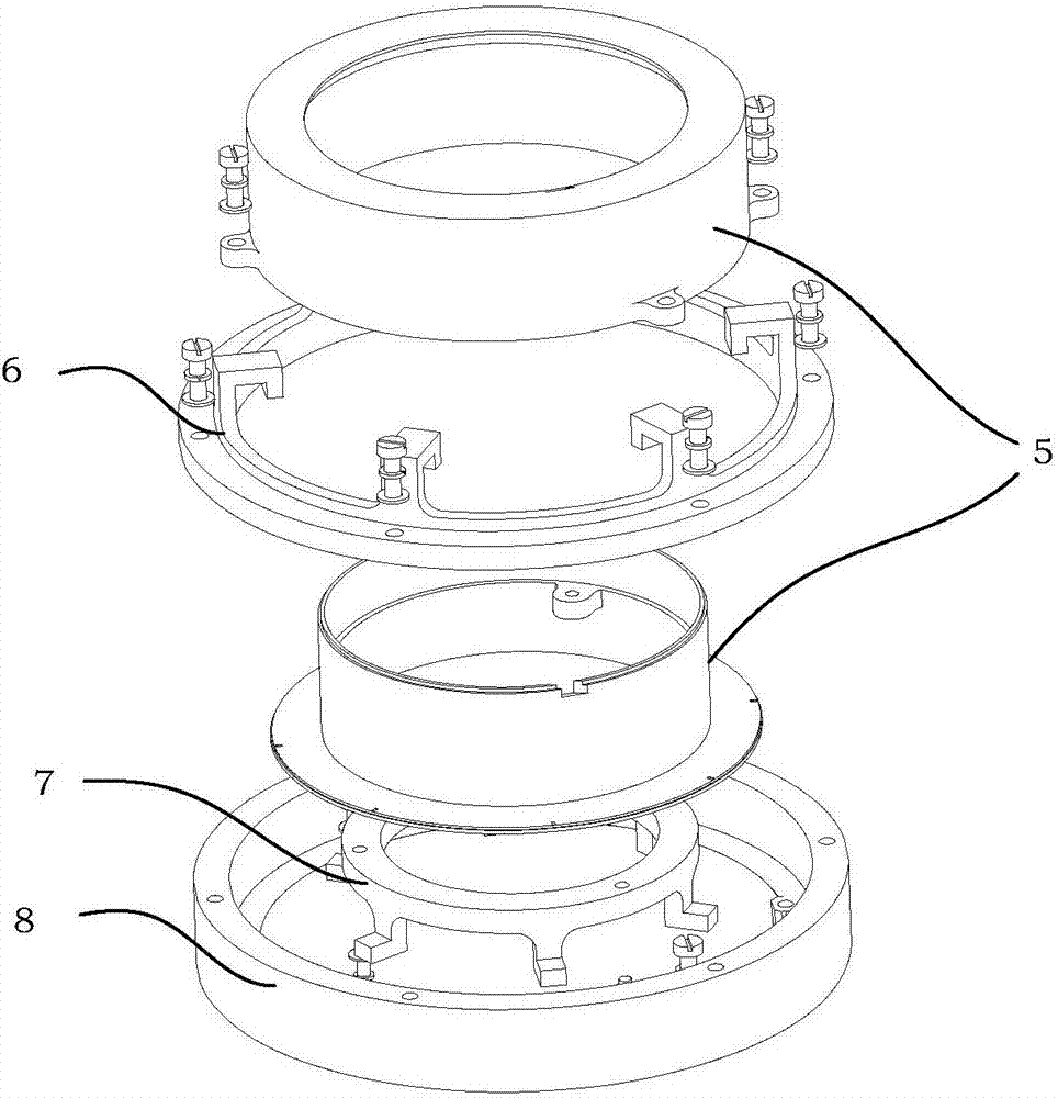
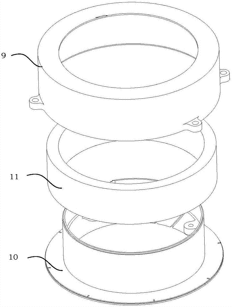
[0043] Welding device of the present invention is used for welding fiber optic gyroscope assembly 5, such as image 3 The structural explosion diagram of the fiber optic gyroscope assembly 5 shown, the fiber optic gyroscope assembly 5 consists of Figure 4 , Figure 4A , Figure 4B Shown gyroscope upper cover 9, Figure 5 , Figure 5A , Figure 5B The gyro base 10 shown with Figure 6 The illustrated fiber optic ring assembly 11 is constructed.

[0044] The gyroscope upper cover 9 is a hollow circular cover, the inner wall of the hollow circular cover is relatively thin, and the inner side and the lower end of the upper end are respectively limited bosses. The bosses vary in thickness and width. There are four external mounting bosses on the outer bottom of the gyro upper cover 9, and the bosses have four mounting through holes. Due to structural cons...


PUM


Abstract

The invention provides a welding device and method for assembling an optical fiber gyro. The deice comprises an optical fiber gyro welding assembly (1), chucks (2), a laser assembly (3) and a platform (4). When the device is adopted for welding an optical fiber gyro, an optical fiber gyro assembly (5) is assembled firstly, an assembled gyro upper cover (9) needs to be welded to the upper side and the lower side of a gyro base (10), and the optical fiber gyro welding assembly (1) is used for pressing the connected gyro upper cover (9) and the gyro base (10). An industrial camera (13) of the laser assembly (3) is used for obtaining weld joint position and images in real time, and a laser (12) is used for completing welding. By means of the welding device and method for assembling the optical fiber gyro, the work efficiency and welding accuracy for structure sealing are improved.

Description

technical field [0001] The invention relates to a welding device and a welding method, in particular to a welding device and a welding method for assembling an optical fiber gyroscope. Background technique [0002] The optical gyroscope works based on the Sagnac effect and realizes the angular velocity measurement of the carrier. Among them, the three-axis integrated fiber optic gyro instrument head is usually composed of a gyro upper cover, a gyro base, an optical fiber ring assembly, and a gyro digital circuit. Fiber optic coils are widely used in fiber optic gyroscopes with medium precision and above due to their high fiber output power, good average wavelength stability, high signal-to-noise ratio and high scale factor accuracy. In the process of producing optical fibers, a single optical fiber needs to be wound into an optical fiber coil, and then the optical fiber coil is fixed on the gyroscope base by dispensing and curing. [0003] For a single optical fiber, befor...

Claims


Application Information

Patent Timeline
Patent Type & Authority Applications(China)
IPC IPC(8): B23K26/08B23K26/28
CPCB23K26/0876B23K26/282
Inventor 张称称许保祥袁韬刘朝阳冯文龙谢海峰王春佳
Owner BEIJING AEROSPACE TIMES OPTICAL ELECTRONICS TECH
Why Eureka
Try Eureka