A light exposure sensor based on reverse series memristor
An inverse series, memristor technology, applied in the field of optical measurement, can solve the problems of small measurement range, complex measurement process, hinder the expansion of performance application range, etc., to achieve the effect of reducing volume and increasing sensitivity
- Summary
- Abstract
- Description
- Claims
- Application Information
AI Technical Summary
Problems solved by technology
Method used
Image
Examples
Embodiment 1
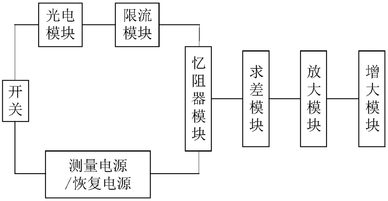
[0034] This embodiment provides an exposure sensor based on a reverse series memristor, such as figure 1 , 6 As shown, it includes a first power supply V1, a second power supply V2, a switch K, a photoelectric module, a current limiting module, a memristor module, a difference module, an amplifying module, and an increasing module;
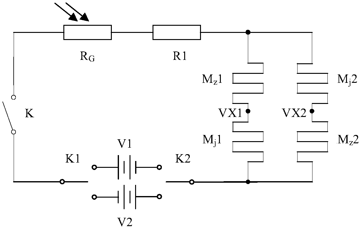
[0035] When the exposure sensor is working, such as figure 2 , the first power supply V1 sequentially forms a circuit with the switch K, the photoelectric module, the current limiting module, and the memristor module;
[0036] When the exposure sensor is in recovery state, such as figure 2 , the second power supply V2 forms a circuit with the switch K, the photoelectric module, the current limiting module, and the memristor module in turn;
[0037]In this embodiment, the first power source V1 and the second power source V2 are switched through single pole double throw switches K1 and K2.
[0038] The memristor module includes a memristor M ...
Embodiment 2
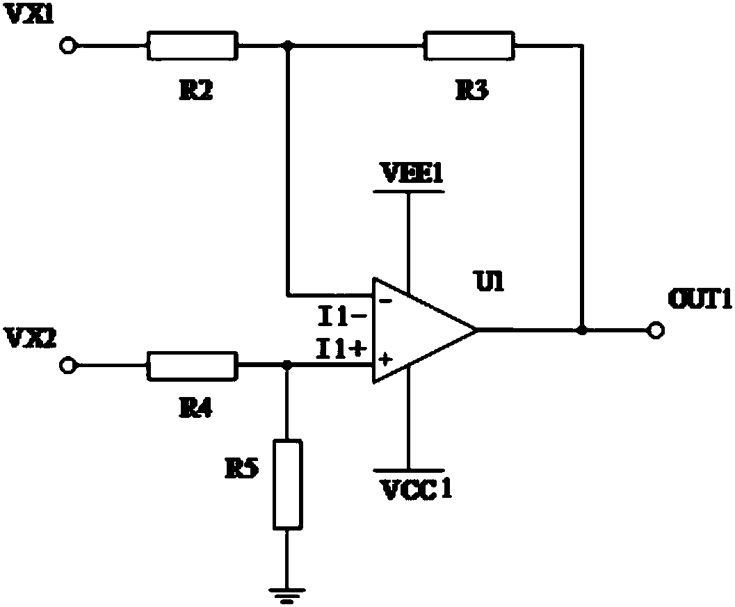
[0045] This embodiment provides a difference module on the basis of Embodiment 1, such as image 3 , including an operational amplifier U1, a resistor R2, a resistor R3, and a resistor R4, the operational amplifier U1 includes an output terminal OUT1, a negative input terminal I1 - , Positive input terminal I1 ﹢ , negative input I1 - Connect to node VX1 through resistor R2, negative input terminal I1 - A node A is drawn between the resistor R2, and the node A is connected to the output terminal OUT1 through the resistor R3, and the positive input terminal I1 ﹢ Two branches are drawn out, one branch is connected to the node VX2 through the resistor R4, and the other branch is connected to the ground through the resistor R5; the operational amplifier U1 also includes a positive power supply VCC1 and a negative power supply VEE1.
[0046] In this embodiment, VCC1 is +12V, and VEE1 is -12V.
Embodiment 3
[0048] This embodiment provides an amplification module on the basis of Embodiment 2, such as Figure 4 , including an operational amplifier U2, a resistor R6, a resistor R7, and a resistor R8, the operational amplifier U2 includes an output terminal OUT2, a negative input terminal I2 - , Positive input terminal I2 ﹢ , negative input I2 - Connect to ground through resistor R7, negative input terminal I2 - A node B is drawn between the resistor R7, and the node B is connected to the output terminal OUT2 through the resistor R8, and the positive input terminal I2 ﹢ The resistor R6 is connected to the output terminal OUT1 of the operational amplifier U1; the operational amplifier U2 also includes a positive power supply VCC2 and a negative power supply VEE2.
[0049] In this embodiment, VCC2 is +12V, and VEE2 is -12V.
PUM
 Abstract
Description
Claims
Application Information
 - R&D
- Intellectual Property
- Life Sciences
- Materials
- Tech Scout
- Unparalleled Data Quality
- Higher Quality Content
- 60% Fewer Hallucinations
Browse by: Latest US Patents, China's latest patents, Technical Efficacy Thesaurus, Application Domain, Technology Topic, Popular Technical Reports.
© 2025 PatSnap. All rights reserved.Legal|Privacy policy|Modern Slavery Act Transparency Statement|Sitemap|About US| Contact US: help@patsnap.com


