Fan case for an aircraft engine

A technology for aircraft engines and fans, applied in the directions of machines/engines, engine components, liquid fuel engines, etc., can solve the problems of complex manufacturing, and achieve the effect of improving strength, simplifying installation process, and improving safety

Active Publication Date: 2017-08-29
FACC
View PDF9 Cites 3 Cited by
  • Summary
  • Abstract
  • Description
  • Claims
  • Application Information

AI Technical Summary

Problems solved by technology

[0007] The construction of many fan cases made of fiber-reinforced plastic is quite complex to manufacture and requires many layers of material, so there is no or only a small weight advantage over metal fan cases

Method used


Image

  • Fan case for an aircraft engine
  • Fan case for an aircraft engine

Examples


Embodiment Construction

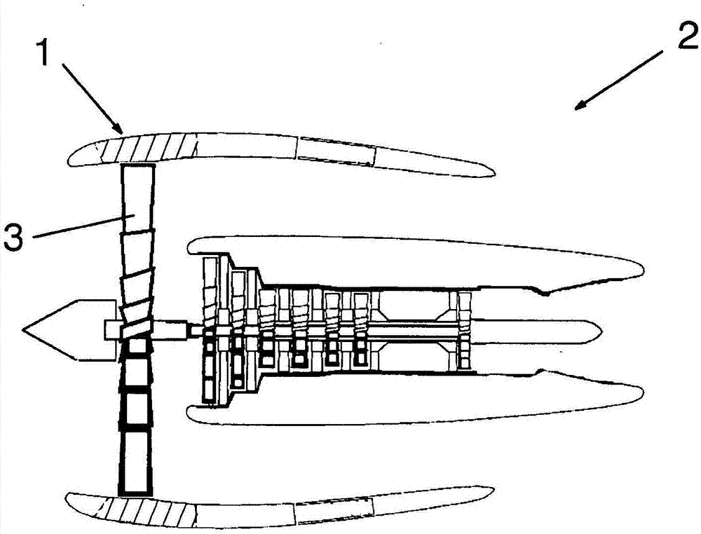
[0023] figure 1 An aircraft engine 2 with a fan housing 1 arranged in the region of the fan 3 is shown in a partially sectioned view. Usually the fan housing 1 comprises a cylindrical casing 1 with a fixing flange and possibly stiffening ribs or the like integrated or fastened thereto. The fan housing 1 is connected to the rest of the engine housing, which in turn is arranged on a corresponding fastening element, usually an airfoil.

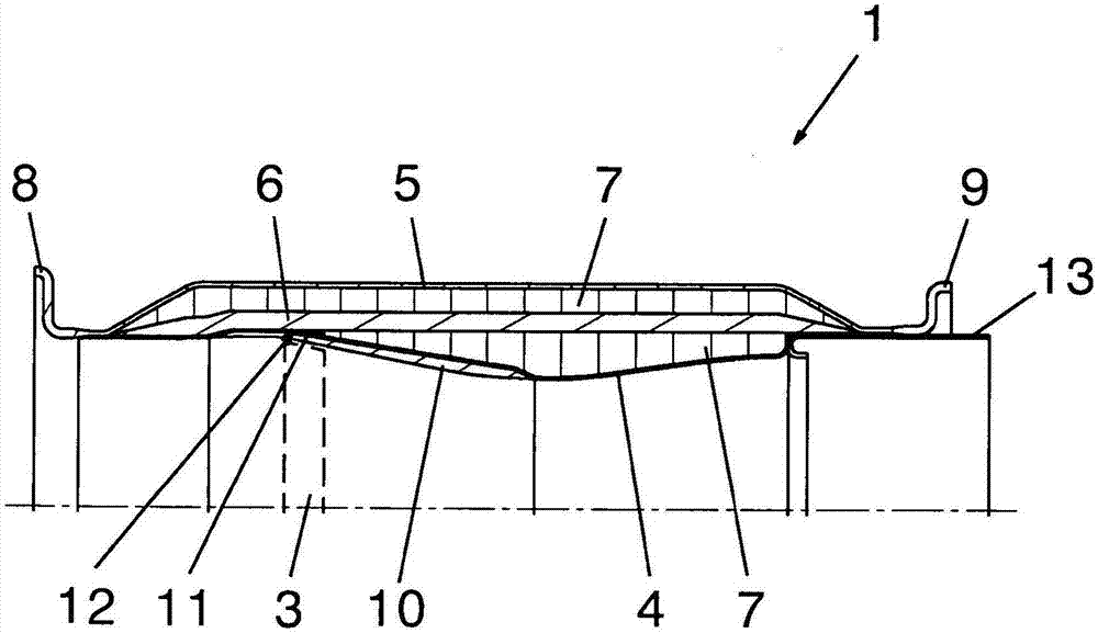
[0024] figure 2 A section of a fan housing 1 constructed according to the invention is shown in section. The fan housing 1 includes an inner layer 4 and an outer layer 5 designed according to the aerodynamic requirements of the aircraft engine 2 and a reinforcing layer 6 arranged between the inner layer 4 and the outer layer 5 and deformation layers arranged on both sides of the reinforcing layer 6 7. Depending on the aircraft engine 2 , the reinforcement layer 6 consists of at least 20 layers of glass-fibre-reinforced plastic and serves pri...


PUM


Abstract

The invention relates to a fan case (1) for an aircraft engine (2) in the region of the fan (3) thereof, comprising a plurality of substantially cylindrically arranged fiber-reinforced plastic layers that are joined together; a reinforcement ply (6) made of glass fiber-reinforced plastic is disposed between an inner layer (4) and an outer layer (5). According to the invention, the reinforcement ply (6) consists of at least 20 plies of glass fiber-reinforced plastic, and deformation layers (7) are disposed on both sides of the reinforcement ply (6), said deformation layers (7) being less strong than the reinforcement ply (6).

Description

technical field [0001] The invention relates to a fan housing or blower housing for an aircraft engine in the region of its fan, comprising a plurality of layers of fiber-reinforced plastic arranged approximately cylindrically and connected to one another, in which Between the layer and the outer layer there is a reinforcement layer made of glass fiber reinforced plastic. Background technique [0002] The fan housing of an aircraft engine is used in the area of ​​the fan to protect the engine from damage in the event of damage to the fan blades separating and to protect passengers in the aircraft from injury. The material chosen for this type of fan housing must be able to absorb the high kinetic energy of the detached fan blades. While metals, especially high-ductile steels or titanium alloys were mainly used earlier for fan housings, plastics have also been used for these aircraft components in recent years. [0003] For example, US 2012 / 0148392 A1 describes a fan casing...

Claims


Application Information

Patent Timeline
Patent Type & Authority Applications(China)
IPC IPC(8): F01D21/04F02K3/06F02C7/04
CPCB29C70/446F01D11/125F01D11/127F01D21/045F01D25/24F02K3/04F02K3/06F02C7/04F05D2300/603B32B17/04B32B17/066B32B17/10073Y02T50/60F04D29/52B32B3/12B32B5/245B32B2250/05B32B2605/18F04D29/526F05D2240/14
Inventor W·费尔斯特E·豪根内德尔K·霍雷希B·施图布纳A·霍尔里格尔
Owner FACC
Why Eureka
Try Eureka