Side-channel blower for an internal combustion engine, comprising a wide interrupting gap

A side channel, internal combustion engine technology, applied in parts of pumping devices for elastic fluids, crankcase ventilation, machines/engines, etc., can solve problems such as rotor jamming, condensate freezing, etc., to reduce noise emission and reduce sensitivity Degree, improve the effect of conveying capacity

Active Publication Date: 2017-08-29
PIERBURG GMBH & CO KG NEUSS
View PDF10 Cites 4 Cited by
  • Summary
  • Abstract
  • Description
  • Claims
  • Application Information

AI Technical Summary

Problems solved by technology

As a result, when such a blower is used in an internal combustion engine, at outside temperatures below freezing, condensation in the gap can freeze and cause the rotor to jam

Method used


Image

  • Side-channel blower for an internal combustion engine, comprising a wide interrupting gap
  • Side-channel blower for an internal combustion engine, comprising a wide interrupting gap
  • Side-channel blower for an internal combustion engine, comprising a wide interrupting gap

Examples


Embodiment Construction

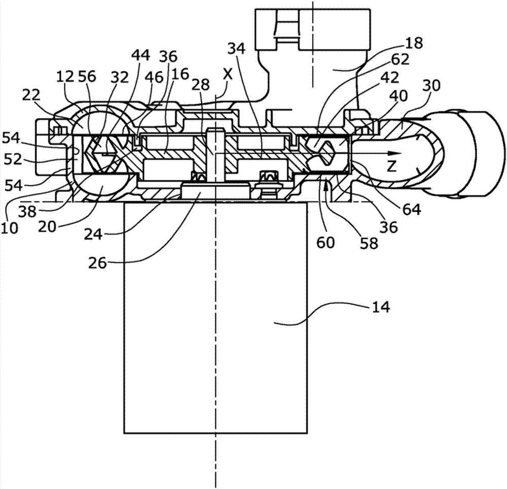
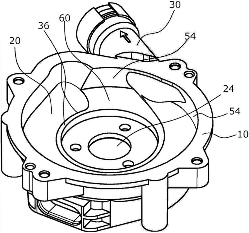
[0023] figure 1 The side-channel blower shown in has a two-part air flow housing consisting of a support housing 10 and a housing cover 12 fastened to the support housing 10, for example with screws. A rotor 16 rotatable by means of a drive 14 is mounted in the bearing housing 10 . The conveyed compressible medium reaches the inside of the side channel blower through the axial inlet 18 designed in the housing cover 12 .

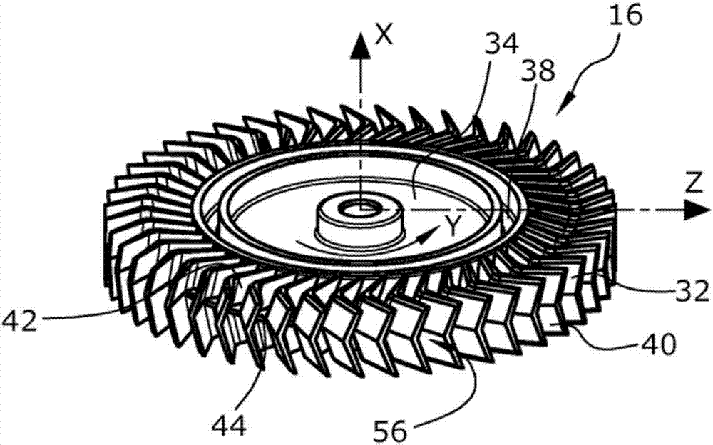
[0024] The medium from the inlet 18 then flows into two substantially annularly extending conveying channels 20, 22, wherein the first conveying channel 20 is designed in the support housing 10, in which the drive shaft 28 of the drive 14 is also mounted in its central hole 24. Bearings 26 , rotor 16 are fixed on drive shaft 28 , and second feed channel 22 is formed in housing cover 12 . Exhaust gas takes place via a tangential outlet 30 formed in the support housing 10 .

[0025] The rotor 16 is mounted between the housing cover 12 and the supporting hous...


PUM


Abstract

Previously known side-channel blowers for an internal combustion engine comprise a fluid-penetrated housing, an impeller (16) that is rotatably arranged in said housing, impeller blades (32) that are formed in the radially outer region of the impeller (16) and are open in the radially outward direction, a radial gap (52) between the impeller (16) and a housing wall (54) that radially surrounds the impeller (16), an inlet (18), an outlet (30), two gas ducts (20, 22) which connect the inlet (18) to the outlet (30), are formed axially opposite the impeller blades (32) in the housing, and are fluidically connected to one another via intermediate spaces between the impeller blades (32), a drive unit (14) for driving the impeller (16), and an interruption zone (58) which is located between the outlet (30) and the inlet (18) and in which the ducts (20, 22) are interrupted in the peripheral direction. In order to be able to manufacture the blower at a lower cost by increasing tolerances and render the blower less prone to the formation of ice and accumulation of dirt without reducing the delivery rate, according to the invention, a radial interrupting gap (64) between the impeller (16) and the radially delimiting housing wall (54) in the entire interruption zone (58) is 0.005 to 0.03 times the diameter of the impeller.

Description

technical field [0001] The invention relates to a side channel blower for an internal combustion engine, comprising: a flow housing, a rotor, rotor blades, a radial gap, an inlet and an outlet and two gas delivery channels connecting the inlet and the outlet, a driving device and a connection between the outlet and the inlet The rotor is rotatably installed in the air flow housing; the rotor blades are designed in the radially outer area of ​​the rotor, and are designed to open radially outward; the radial gap is between the rotor and the radial between the housing walls surrounding the rotor; the gas delivery channels are arranged axially opposite the rotor blades in the gas flow housing and are in fluid communication with each other via the gaps between the rotor blades; the rotor can be driven by means of the drive; the delivery channels Cut off in the circumferential direction in the cut-off zone. Background technique [0002] Side channel blowers or pumps are well know...

Claims


Application Information

Patent Timeline
Patent Type & Authority Applications(China)
IPC IPC(8): F04D23/00F04D29/16F04D29/26F04D29/40F04D5/00
CPCF04D23/008F04D29/161F04D29/26F04D29/403F04D5/007F05D2250/53F01M13/02F01M2013/026F04D29/30F04D29/4206F04D29/441F04D29/663F04D29/667
Inventor M.布特罗斯-米卡希尔R.彼得斯
Owner PIERBURG GMBH & CO KG NEUSS
Why Eureka
Try Eureka