Sand blasting machine for transmission shaft

A transmission shaft and sandblasting machine technology, which is applied in the direction of abrasive jetting machine tools, used abrasive processing devices, abrasives, etc., can solve problems affecting surface finish and surface accuracy, and affect safety hazards of automobile performance, so as to improve accuracy Performance and stability, high degree of automation, simple and compact structure

Inactive Publication Date: 2017-09-01
肇庆市端州区图恩斯科技有限公司
View PDF5 Cites 2 Cited by
  • Summary
  • Abstract
  • Description
  • Claims
  • Application Information

AI Technical Summary

Problems solved by technology

However, whether it is liquid sandblasting or high-pressure water jet sandblasting, the principle is to use the high-speed impact of abrasives to remove surface attachments. If the splines at both ends of the constant velocity universal joint drive shaft are not protected, they will be damaged by abrasives. Imprints will be produced due to impact, which will affect the surface finish and surface accuracy, thereby affecting the performance of the car and even causing safety hazards
At present, there is no equipment for blasting surface cleaning that can meet the requirements

Method used


Image

  • Sand blasting machine for transmission shaft
  • Sand blasting machine for transmission shaft
  • Sand blasting machine for transmission shaft

Examples


Embodiment Construction

[0024] The present invention will be further described in detail below in conjunction with the accompanying drawings and specific embodiments.

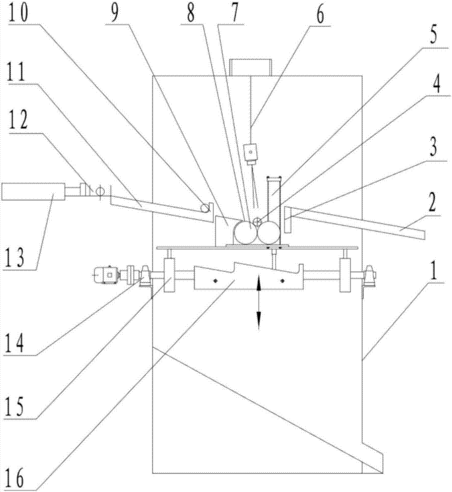
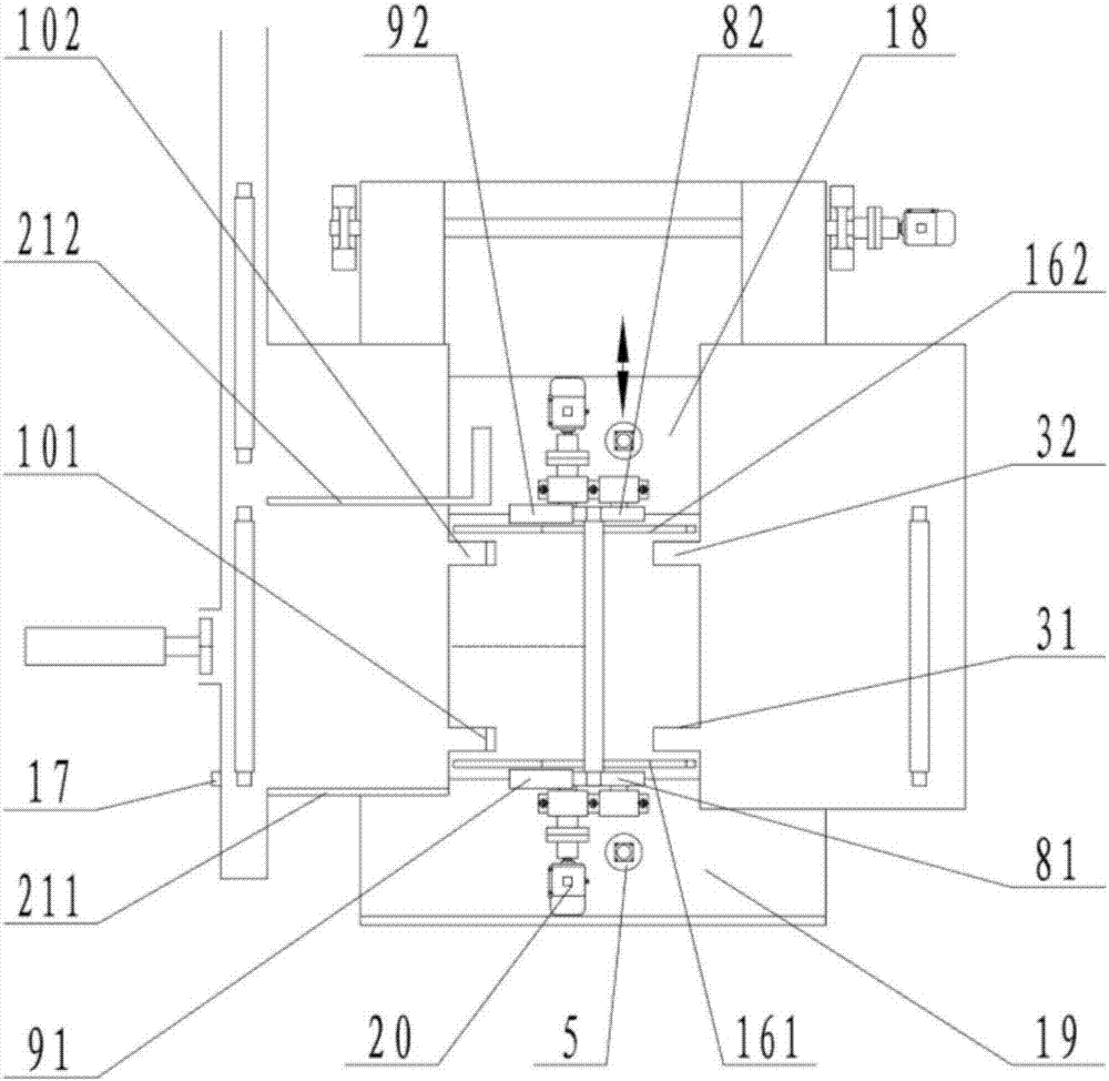
[0025] Such as figure 1 with figure 2 As shown, the sandblasting machine for the transmission shaft of the present invention includes a frame 1 and a sandblasting mechanism 6 installed on the frame 1. The sandblasting mechanism 6 includes a reciprocating mechanism positioned at the top of the frame 1 and a reciprocating The spray head connected by the kinematic mechanism, the reciprocating stroke, reciprocating speed, spraying distance and spraying angle of the sandblasting mechanism 6 are adjustable. There are two sets of positioning assemblies 8 for placing the transmission shaft 4 below the sandblasting mechanism 6. The connecting lines of the two sets of positioning assemblies 8 are parallel to the horizontal plane. The distance between the two sets of positioning assemblies 8 is equal to the distance between the splines at both...


PUM


Abstract

The invention discloses a sand blasting machine for a transmission shaft. The sand blasting machine comprises a machine frame and a sand blasting mechanism arranged on the machine frame, wherein two sets of positioning assemblies allowing the transmission shaft to be placed are arranged under the sand blasting mechanism; the distance between the two sets of positioning assemblies is equal to that between splines arranged at two ends of the transmission shaft; each set of positioning assembly comprises two rotating parts which are oppositely arranged; a spacing is reserved between the two rotating parts, and is smaller than the diameter of a position wherein the spline is formed, of the transmission shaft. The sand blasting machine disclosed by the invention is simple in structure, and uniform in sand blasting; and the situation that splines at two ends of the transmission shaft are impacted by grinding materials can be avoided.

Description

technical field [0001] The invention mainly relates to the field of sandblasting equipment, in particular to a sandblasting machine used for transmission shafts. Background technique [0002] The constant velocity universal joint drive shaft is one of the main components in the chassis transmission system, and it is often used in cars with front-engine front-wheel drive, front-engine rear-wheel drive or four-wheel drive. Damage, wear, corrosion, deformation and loss of dynamic balance of drive shaft parts will cause abnormal noise and vibration during driving, and in severe cases, it will cause damage to related components and cause safety accidents. [0003] Since the constant velocity universal joint transmission shaft of the automobile is exposed in the atmosphere, it is often corroded and rusted due to atmospheric moisture or pollutants. , Before the anti-corrosion treatment of the surface coating, it is necessary to remove the oil, rust and other attachments on the sur...

Claims


Application Information

Patent Timeline
Patent Type & Authority Applications(China)
IPC IPC(8): B24C1/08B24C3/02B24C9/00
CPCB24C1/086B24C3/02B24C9/00
Inventor 郭少明
Owner 肇庆市端州区图恩斯科技有限公司
Why Eureka
Try Eureka