Precision tubular microporous aerator mounting and detecting system and method

A technology of microporous aerator and detection system, which is applied in chemical instruments and methods, water aeration, testing of machine/structural components, etc. Assembly error uncertainty and other problems, to achieve the effect of reliable performance, low price, and guaranteed cleanliness

Active Publication Date: 2017-09-01
葛洲坝水务投资有限公司 +1
View PDF5 Cites 2 Cited by
  • Summary
  • Abstract
  • Description
  • Claims
  • Application Information

AI Technical Summary

Problems solved by technology

[0002] The most important equipment in the biological treatment system in the sewage treatment plant is the blast aeration system. The core element in the blast aeration end system is the aeration membrane. The service life of the aeration membrane is 3 to 6 years. The diaphragm must be replaced at the end of its service life, and the installation process of replacing the aeration diaphragm is a very complicated and cumbersome process
In sewage treatment plants, various aeration devices are used in the biological treatment stage. Among several aeration devices, the tubular aeration device is commonly used. An aeration diaphragm is composed of two single-ear stepless clamps. Composed of aeration diaphragms, tens of thousands of single-ear stepless clamps need to be installed once replaced. First, the water and sludge in the 4-6 meter deep biological pool need to be drained, which is time-consuming and laborious. Aeration diaphragms Once it is replaced, it will be used continuously for 24 hours. If any aeration pipe leaks, it needs to be replaced, and the water in the biological pool needs to be drained again. Therefore, the quality requirements for the installation of the aeration diaphragm are very strict. Clamps not only have low work efficiency, but also have great uncertainty in assembly errors. The installation of aeration pipes has a small application range and no mature supporting products. It is imperative to solve the installation quality requirements and reduce the work intensity of operators.

Method used


Image

  • Precision tubular microporous aerator mounting and detecting system and method
  • Precision tubular microporous aerator mounting and detecting system and method
  • Precision tubular microporous aerator mounting and detecting system and method

Examples


Embodiment 1

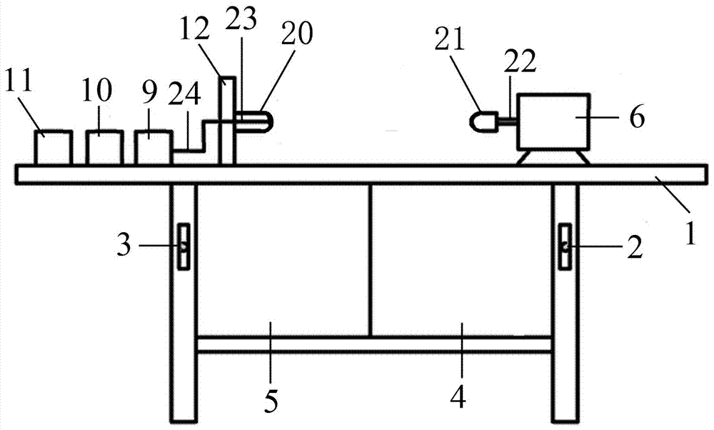
[0031] It consists of a workbench (1), installation facilities (4) and testing facilities (5). The installation facilities (4) and testing facilities (5) are set on the workbench (1). By installing the pneumatic switch (2) and the testing switch (3) Installation and testing of the conversion aeration diaphragm.

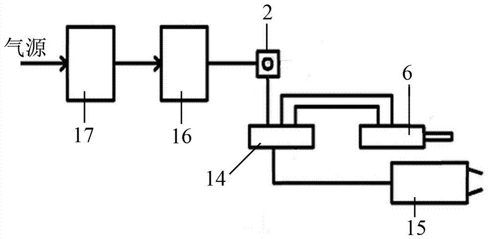
[0032] The installation facility (4) consists of installing pneumatic switches (2), cylinders (6), pneumatic valves (14), pneumatic clamps (15), filters (16) and pressure reducing valves (17), through air compressors or blowers The gas source is generated, and the gas source is connected to the pressure reducing valve (17) through the pipeline. The pressure reducing valve (17) is made of stainless steel. The pressure reducing valve (17) keeps the gas source stable and the work force consistent. ) to filter out impurities in the gas source and keep the gas source clean. The filter (16) adopts a film type pressure reducing valve, a pilot piston type gas pressure reducin...

Embodiment 2

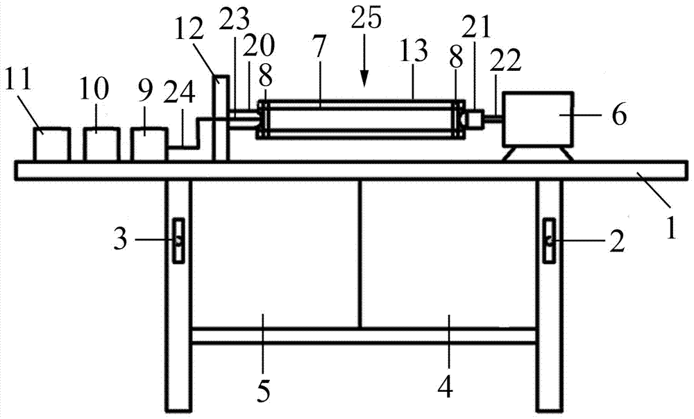
[0034] The pneumatic valve (14) is respectively connected with the cylinder (6) and the pneumatic clamp (15). The cylinder (6) complies with the international standard IS06430 and international standard 6431. The end of the push rod (22) of the cylinder (6) is set Movable plugging (21), one end of the aeration pipe (7) of the tubular microporous aerator (25) is installed at the end of the movable plugging (21), and the end of the movable plugging (21) is connected with the aeration The ends of the pipes (7) coincide, and the ends of the movable plugging (21) are tightly sealed to block the ends of the aeration pipes (7) of the tubular microporous aerator (25), and the pneumatic pliers (15) lock Close clamp (8), clamp (8) adopts single-ear stepless clamp.

[0035] The detection facility (5) consists of a detection switch (3), a gas flow meter (9), a time relay (18) and a solenoid valve (19). The power supply is connected to the detection switch (3) through a circuit, and the de...

Embodiment 3

[0037] The installation facility (4) and testing facility (5) are connected with the main controller (10). The main controller (10) adopts PC or industrial control machine. The installation facility (4) and testing facility (5) aerate the installation Tube (7) data information and detection data information of aeration tube (7) is transmitted to the main controller (10), and the main controller (10) collects data information, stores data information, sorts out each aeration tube (7) data information and analysis data information, and print out the data information of each aeration pipe (7) through the printer (11).

[0038] A gas flowmeter (9), a main controller (10), a printer (11), a support frame (12) and a cylinder (6) are fixedly arranged on the workbench (1), and the support frame (12) and the cylinder (6) are relatively installed. Located at both ends of the workbench (1), the other end of the workbench (1) is fixedly installed with a support frame (12), and a fixed blo...


PUM


Abstract

The invention discloses a precision tubular microporous aerator mounting and detecting system and a precision tubular microporous aerator mounting and detecting method. The precision tubular microporous aerator mounting and detecting system consists of a workbench, a mounting facility and a detecting facility, wherein the mounting facility and the detecting facility are arranged on the workbench; through a mounting pneumatic switch and a detection switch, mounting and detection of tubular microporous aerators are switched; through an air compressor or an air blower, an air source is generated; the air source is connected with a pressure reducing valve through a pipeline; a filter is connected to a pneumatic valve; the mounting pneumatic switch is mounted between the filter and the pneumatic valve; the mounting pneumatic switch controls the air source entering the pneumatic valve; the mounting facility and the detecting facility are connected with a main controller; and the main controller collects, stores, sorts and analyzes data information of each tubular microporous aerator. The precision tubular microporous aerator mounting and detecting system is scientific in structure, reliable in performance, easy to manufacture, convenient to use, easy to operate and precision in mounting, and is especially applicable to urban sewage treatment, new construction and expansion of a large factory and reconstruction of an old aeration tank.

Description

technical field [0001] The invention relates to an installation system of a tubular microporous aerator, in particular to an installation and detection system and an installation and detection method of a precise tubular microporous aerator. Background technique [0002] The most important equipment in the biological treatment system in the sewage treatment plant is the blast aeration system. The core element in the blast aeration end system is the aeration membrane. The service life of the aeration membrane is 3 to 6 years. The diaphragm must be replaced at the end of its service life, and the installation process of replacing the aeration diaphragm is a very complicated and cumbersome process. In sewage treatment plants, various aeration devices are used in the biological treatment stage. Among several aeration devices, the tubular aeration device is commonly used. An aeration diaphragm is composed of two single-ear stepless clamps. Composed of aeration diaphragms, tens o...

Claims


Application Information

Patent Timeline
Patent Type & Authority Applications(China)
IPC IPC(8): C02F7/00G01M13/00C02F3/12
CPCC02F3/1278C02F7/00C02F2201/002G01M13/00Y02W10/10
Inventor 张雪洪尉凤珍运霖霖黄晋李广楠袁耀
Owner 葛洲坝水务投资有限公司
Why Eureka
Try Eureka