Wall structure with no cold bridge

A wall structure and wall technology, applied in the direction of walls, building components, building structures, etc., can solve the problems of reduced thermal insulation performance, increased sound insulation effect, increased construction difficulty, etc., to achieve anti-corrosion protection, safe and reliable installation process, The effect of preventing the entry of water and dust

Inactive Publication Date: 2017-09-01
HEBEI ZHUOQIU IND CO LTD
View PDF9 Cites 4 Cited by
  • Summary
  • Abstract
  • Description
  • Claims
  • Application Information

AI Technical Summary

Problems solved by technology

Although the thermal insulation wall not only has strong firmness, but also increases the sound insulation effect, the complex structure of the wall increases the difficulty of construction
[0004] In the above technical solutions, especially after the thermal insulation wall is assembled, the thermal insulation performance is reduced, and the connection between the wall and the

Method used


Image

  • Wall structure with no cold bridge
  • Wall structure with no cold bridge
  • Wall structure with no cold bridge

Examples


Embodiment 1

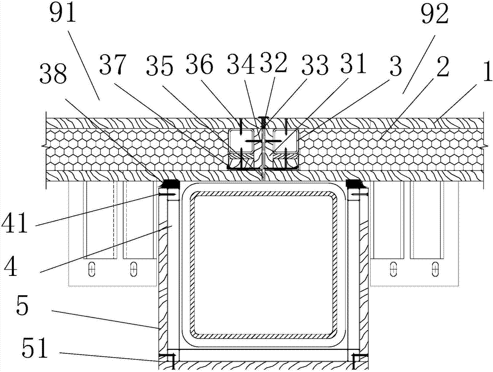
[0024] see figure 1 As shown, it is a schematic diagram of Embodiment 1 of the wall structure without cold bridge of the present invention. In this embodiment, the first wall module 91 and the second wall module 92 include panels 1 on both sides and panels 1 Inner insulation layer 2.

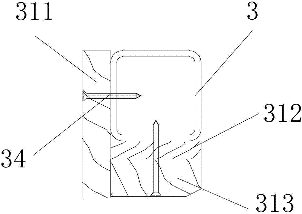
[0025] Set the outer wall keel steel pipe 3 at the end of each wall formwork, the upper side of the outer wall keel steel pipe 3 is in contact with the panel 1 on the upper layer of the wall module; please combine figure 2 As shown, a structural plate 31 is provided on one side and the lower part of the outer wall keel steel pipe 3 . When two adjacent wall formworks are connected, in this embodiment, when the first wall module 91 and the second wall module 92 are connected, between the outer wall keel steel pipes 3 at the ends of the two wall modules and The structural plate 31 is arranged between the outer wall keel steel pipe 3 and the lower panel 1 of the wall module.

[0026] Please comb...

Embodiment 2

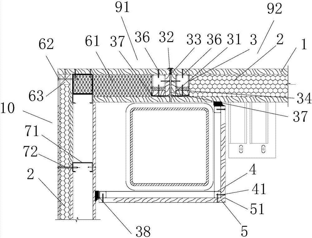
[0037] The difference between this embodiment and the above-mentioned embodiments is that a partition wall 10 is provided in this embodiment, and the thermal insulation layer of the outer wall at the connection between the partition wall 10 and the outer wall is filled with rock wool board 61 with a small thermal conductivity.

[0038] A spacer 63 is also arranged at the corner of the partition wall 10 and the outer wall. The spacer 63 is arranged at the end of the insulation layer of the partition wall 10 . The spacer 63 and the rock wool board 61 are connected by the fourth screw 62 .

[0039] The partition wall 10 is also provided with an inner wall keel steel pipe 71 , and the insulation layer and the inner wall keel steel pipe 71 are connected by fifth screws 72 .

[0040] In this embodiment, an elastic fireproof sealant 38 is applied to the connection between the fireproof board 5 and the outer wall and the partition wall.

[0041] The invention effectively prevents the ...


PUM


Abstract

The invention discloses a wall structure with no cold bridge. The wall structure comprises a first wall module and a second wall module. The two wall modules each comprise panels on the two sides and a heat preservation layer arranged on the inner sides of the panels. The end of each wall module is provided with an outer wall keel steel pipe. The upper sides of the outer wall keel steel pipes make contact with the panels on the upper layers of the wall modules. One side and the lower portion of each outer wall keel steel pipe is each provided with a structural plate. The seam between every two adjacent structural plates of the two outer wall keel steel pipes is filled with a polyethylene foam slat, an elastic sealant and a rubber strip from top to bottom. According to the wall structure, by arranging the rubber strips and the elastic sealants at the butt joint seams of outer wallboards, water and dust are effectively prevented from entering, and the anti-corrosion and cleaning effects are achieved for protecting internal steel components, so that a heat preservation structure integrated board achieves the purposes of mechanical and durable qualification, fire prevention, heat preservation, energy saving, environmental protection and safe and reliable mounting process.

Description

technical field [0001] The invention relates to the technical field of wall assembly, in particular to a wall structure without a cold bridge. Background technique [0002] Most of the walls in the prior art are spliced, and the composite wall panels are divided into small pieces, which are assembled into large pieces through the small pieces, and finally assembled into the whole wall. When forming a wall, it is often directly connected through the side of the wall. [0003] Chinese patent CN103321319A discloses a thermal insulation wall, including a main wall layer, on the outside of the main wall layer, a thermal insulation board layer, a hot-dip galvanized steel wire mesh layer, a sound insulation board layer, a glass fiber mesh layer and an insomnia layer are sequentially arranged. paint layer. Although the thermal insulation wall not only has strong firmness, but also increases the sound insulation effect, the complex structure of the wall increases the difficulty of ...

Claims


Application Information

Patent Timeline
Patent Type & Authority Applications(China)
IPC IPC(8): E04B2/74E04B1/66E04B1/80E04B1/94
CPCE04B2/7403E04B1/6812E04B1/80
Inventor 李敬华严英乾
Owner HEBEI ZHUOQIU IND CO LTD
Why Eureka
Try Eureka