Checking system and checking method for integrated partial discharge live detection device
A technology of live detection and partial discharge, which is applied in the direction of measuring devices, measuring electrical variables, instruments, etc., can solve the problems that live detection devices cannot adapt to the electromagnetic interference environment of substations, the detection effectiveness is reduced, and the environment is complex, so as to reduce the threshold and total The effect of volume reduction and simple operation
- Summary
- Abstract
- Description
- Claims
- Application Information
AI Technical Summary
Problems solved by technology
Method used
Image
Examples
Embodiment 1
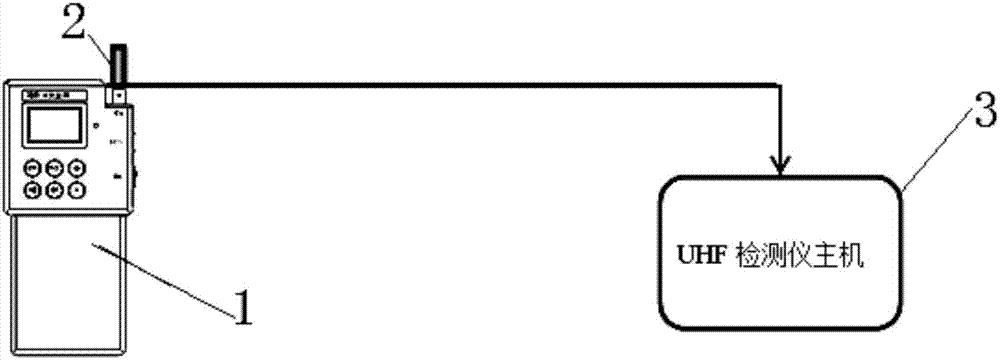
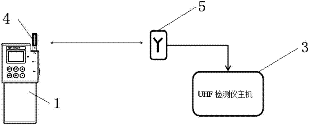
[0067] Such as image 3 As shown, the integrated partial discharge charging detection device verification system provided by the embodiment of the present application includes: a pulse generator 1 , a UHF detector host 3 , a transmitting antenna 4 , and a UHF receiving sensor 5 .
[0068] The output voltage of the pulse generator 1 should be between 5V-200V, set 10V / 20V / 50V / 100V / 150V / 200V, etc., the rising edge of the input pulse waveform should meet ≤600ps, and the pulse width should be between 4ns-100ns. The pulse generator 1 should be designed to be hand-held. The output amplitude stability of the pulse generator 1 is required to reach more than 95%.
[0069] The detection of UHF partial discharge belongs to non-contact measurement, so the coupling device is essentially the transmitting antenna 4, and the transmitting antenna 4 can use an end probe. After the pulse generator 1 is installed with the transmitting antenna 4, it can be called a transmitting device, and the di...
Embodiment 2
[0077] Such as Figure 5 As shown, the integrated partial discharge live detection device verification system provided by the embodiment of the present application includes: pulse generator 1, HF detector host 19, coaxial cable 6, matching tooling 7, 50Ω matching head 8, RFCT ferrule 9 .
[0078] The pulse generator 1 is connected to the HF detector host 19 through the coaxial cable 6, and the coaxial cable 6 is equipped with a matching tool 7, a 50Ω matching head 8, and an RFCT ferrule 9.
[0079] The pulse polarity of pulse generator 1 can be positive and negative conversion, the rise time of the pulse waveform is not more than 0.1us, the fall time is not less than 100us, the peak value of the output pulse voltage is adjustable in the range of 10mV-5V, and the adjustment range is divided into 10mV / 20mV / 50mV / 1V / 2V / 3V / 4V / 5V several gears are enough. The pulse generator 1 should be designed to be hand-held. The output amplitude stability of the pulse generator 1 is required...
Embodiment 3
[0088] Such as Figure 6 As shown, the integrated partial discharge live detection device verification system provided by the embodiment of the present application includes: a pulse generator 1 , a coaxial cable 6 , a 50Ω matching head 8 , a metal plate 10 , and a TEV detector host 11 .
[0089] The pulse generator 1 is connected to the host 11 of the TEV detector through the coaxial cable 6 , a 50Ω matching head 8 is connected in series on the coaxial cable 6 , and a metal plate 10 is connected in parallel on the coaxial cable 6 .
[0090] The pulse polarity of pulse generator 1 can be positive and negative conversion, the rise time of the pulse waveform is not more than 0.1us, the fall time is not less than 100us, the peak value of the output pulse voltage is adjustable in the range of 10mV-5V, and the adjustment range is divided into 10mV / 20mV / 50mV / 1V / 2V / 3V / 4V / 5V several gears are enough. The pulse generator 1 should be designed to be hand-held, and the output amplitude s...
PUM
 Abstract
Description
Claims
Application Information
 - R&D
- Intellectual Property
- Life Sciences
- Materials
- Tech Scout
- Unparalleled Data Quality
- Higher Quality Content
- 60% Fewer Hallucinations
Browse by: Latest US Patents, China's latest patents, Technical Efficacy Thesaurus, Application Domain, Technology Topic, Popular Technical Reports.
© 2025 PatSnap. All rights reserved.Legal|Privacy policy|Modern Slavery Act Transparency Statement|Sitemap|About US| Contact US: help@patsnap.com


