
Non-doped high-efficiency organic photovoltaic cells

An organic photovoltaic cell, high-efficiency technology, applied in the direction of circuits, electrical components, electric solid devices, etc., can solve the problems of increasing heterojunction interface, complex preparation process, and complex battery structure, so as to improve energy conversion efficiency and battery structure. The effect of increasing the number of simple, dissociated interfaces

Active Publication Date: 2019-09-10
江苏鸿洹新能源有限公司
View PDF3 Cites 0 Cited by
  • Summary
  • Abstract
  • Description
  • Claims
  • Application Information

AI Technical Summary

Problems solved by technology

The bulk heterojunction structure greatly increases the interface of the heterojunction, which can effectively promote the dissociation of excitons, but the structure of the battery is also more complicated.
At the same time, the performance of the battery is greatly affected by the mixing ratio of the two donor and acceptor materials. It is necessary to precisely control the doping ratio of the donor or acceptor, which increases the difficulty of device preparation and is not conducive to large-scale industrial production.
The present invention aims to overcome the problems of few exciton dissociation interfaces, low battery efficiency and complex preparation process of hybrid heterojunction structure organic photovoltaic cells in the background technology, and proposes a new type of non-doped Heterogeneous High Efficiency Organic Photovoltaic Cells

Method used


Image

  • Non-doped high-efficiency organic photovoltaic cells

Examples


Embodiment 1

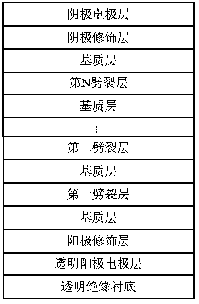
[0029]Non-doped high-efficiency organic photovoltaic cells, the device structure is: transparent insulating substrate Glass 1.2 mm / transparent anode electrode layer ITO 200 nm / anode modification layer MoO3 5 nm / C70 15 nm / first split layer TAPC 5 nm / C70 15nm / second split layer TAPC 5 nm / C70 15 nm / third split layer TAPC 5 nm / C70 15 nm / cathode modification layer Bphen 5 nm / cathode electrode Al 100 nm, wherein the matrix layer is 60 nm of C70, There are three splitting layers in the battery, that is, N=3, which can form six organic heterojunction interfaces for exciton dissociation. The distance between the first splitting layer and the MoO3 anode modification layer is greater than 5 nm, and the third splitting layer The distance from the Bphen cathode modification layer is greater than 5 nm, the distance between the first split layer and the second split layer is greater than 5 nm, and the distance between the second split layer and the third split layer is greater than 5 n...

Embodiment 2

[0031] Non-doped high-efficiency organic photovoltaic cells, the device structure is: transparent insulating substrate Glass 1.2 mm / transparent anode electrode layer ITO 200 nm / anode modification layer MoO3 5 nm / C60 10 nm / first splitting layer NPB 2 nm / C60 10 nm / second splitting layer NPB 2 nm / C60 10 nm / third splitting layer NPB 2 nm / C60 10 nm / fourth splitting layer NPB 2nm / C60 10 nm / cathode modification layer BCP 10 nm / cathode electrode Ag 80 nm, in which the matrix layer is 40 nm C60, there are four splitting layers in the battery, that is, N=4, which can form 8 organic heterojunction interfaces for exciton dissociation.

Embodiment 3

[0033] N=1, Glass 1.2 mm / transparent anode electrode layer ITO 200 nm / anode modification layer MoO3 5 nm / C70 25nm / first splitting layer TPD 5 nm / C70 25 nm / cathode modification layer BCP 10 nm / cathode electrode Ag 80 nm, where the matrix layer is 50 nm C70, and the splitting layer in the cell is 5 nm TPD, which can form two organic heterojunction interfaces for exciton dissociation.


PUM


Abstract

The invention discloses a non-doped high-efficiency organic photovoltaic cell, which comprises a transparent insulating substrate, a transparent anode electrode layer sequentially stacked on the transparent insulating substrate, an anode modification layer, a matrix layer, a cathode modification layer, and a cathode electrode layer , and several splitting layers arranged in the matrix layer. The splitting layer provides several dissociation interfaces for excitons, which can effectively improve the energy conversion efficiency of organic solar cells.

Description

technical field [0001] The invention belongs to the technical field of photoelectric conversion devices, and in particular relates to a non-doped high-efficiency organic photovoltaic cell. Background technique [0002] The research on organic solar cells began in 1958. Kearns and Calvin sandwiched magnesium phthalocyanine dye (MgPc) between two electrodes with different work functions to make a "sandwich" structure, thus obtaining an open circuit voltage of 200 mV, but Its short-circuit current output is very low, so its energy conversion efficiency is relatively low. This single-layer organic solar cell structure was replaced by C.W.Tang in 1986 with a double-layer heterojunction structure, which achieved an energy conversion efficiency of 1%. The reason why the energy conversion efficiency has been greatly improved is that the double-layer heterojunction structure provides an efficient interface for exciton splitting, that is to say, the double-layer heterostructure allow...

Claims


Application Information

Patent Timeline
Patent Type & Authority Patents(China)
IPC IPC(8): H01L51/42
CPCH10K30/00Y02E10/549
Inventor 晋佳佳
Owner 江苏鸿洹新能源有限公司
Learn More