
Boiler device for preparing steam

A boiler equipment and steam technology, which is applied in steam boilers, steam generation, lighting and heating equipment, etc., can solve the problems of low steam generation efficiency, slow steam circulation speed, single boiler structure, etc., achieve simple structure, reduce production costs, The effect of improving production efficiency

Pending Publication Date: 2017-09-05
容县润达家具有限公司
View PDF5 Cites 2 Cited by
  • Summary
  • Abstract
  • Description
  • Claims
  • Application Information

AI Technical Summary

Problems solved by technology

[0002] At present, steam drying methods are more and more used in the production of enterprises, especially in the wood processing industry, most enterprises use steam to dry wood boards, and for the acquisition of steam, many enterprises adapt measures to local conditions and make A closed boiler with water is used to heat the boiler with the remaining wood, so that the water in the furnace boils to generate steam, and then the steam is led to the drying room to dry the wood boards. Although this method is simple and fast, However, because the structure of the boiler is too simple, its steam generation speed is slow and the amount is small, that is, the steam generation efficiency is low, the steam circulation speed is slow, and the heat is insufficient, resulting in waste of resources, and the exhaust gas is directly discharged, resulting in large environmental pollution. Therefore, the traditional Boilers for producing steam can no longer meet the production needs of enterprises

Method used


Image

  • Boiler device for preparing steam
  • Boiler device for preparing steam
  • Boiler device for preparing steam

Examples


Embodiment Construction

[0023] The present invention will be further described below with reference to the specific embodiments in the accompanying drawings.

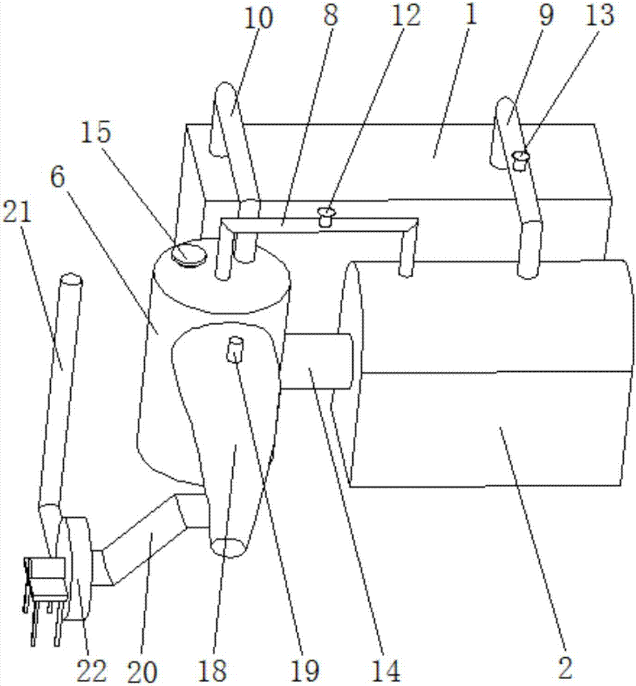
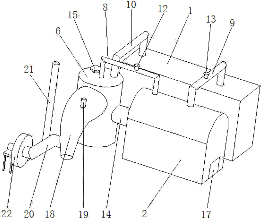
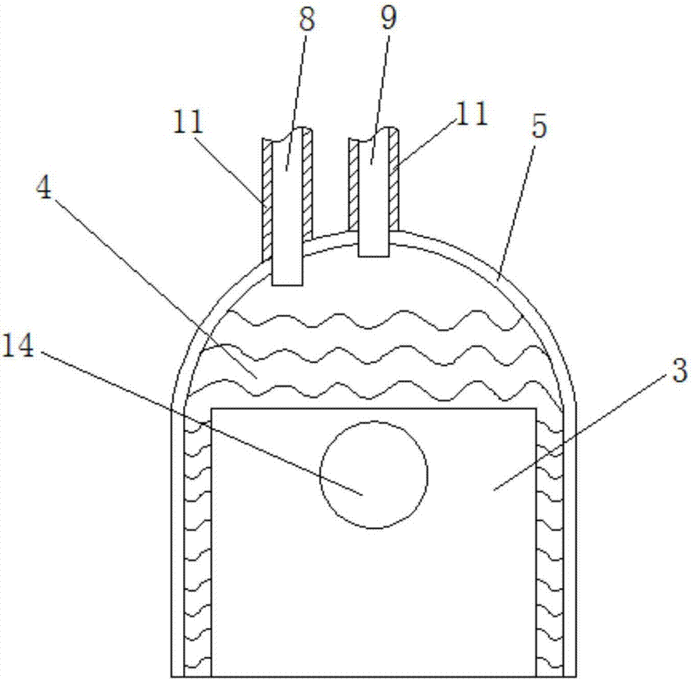
[0024] see Figure 1-4 , a boiler equipment for producing steam according to the present invention, including a furnace body 2 located on one side of the drying room 1, which is used to burn firewood to generate steam, and the furnace body 2 is as close as possible to the drying room 1 to avoid heat loss of steam , a combustion chamber 3 for accommodating firewood is provided in the furnace body 2, and a boiling water pool 4 that completely covers the combustion chamber 3 is provided in the furnace body 2 above the combustion chamber 3, and the boiling water pool 4 holds hot water to make the heat The water is in full contact with the outer surface of the combustion chamber 3, and an interlayer 5 covering the boiling water pool 4 is provided between the boiling water pool 4 and the shell of the body of heater 2, that is, the interlayer 5 wraps...


PUM


Abstract

The invention discloses a boiler device for preparing steam. The boiler device comprises a furnace body located at one side of a drying room, wherein a combustion chamber is arranged in the furnace body; a boiling water pond for completely covering the combustion chamber is arranged above the combustion chamber; an interlayer for covering the boiling water pond is arranged between the boiling water pond and the shell; an exhaust furnace communicating with the combustion chamber is arranged at one end of the furnace body; a preheating pond capable of utilizing afterheat of combustion tail gas for heating is arranged at the upper part of an inner cavity of the exhaust furnace; and a circulating pipe for communicating the preheating pond, the boiling water pond and a steam pipe of the drying room to form a moisture cycle is also arranged on the furnace body. The boiler device is simple in structure and convenient to prepare; the contact area of the boiling water pond and the combustion chamber is expanded; hot water is preheated by reasonably utilizing the tail gas and flows into the boiling water pond in cycle; the energy of combustion is fully utilized; the preparation efficiency and flow of the steam are improved; the production cost is reduced; and the requirements of energy conservation and environment protection are met.

Description

technical field [0001] The invention relates to the technical field of boiler equipment, more specifically, it relates to a boiler equipment for producing steam. Background technique [0002] At present, steam drying methods are more and more used in the production of enterprises, especially in the wood processing industry, most enterprises use steam to dry wood boards, and for the acquisition of steam, many enterprises adapt measures to local conditions and make A closed boiler with water is used to heat the boiler with the remaining wood, so that the water in the furnace boils to generate steam, and then the steam is led to the drying room to dry the wood boards. Although this method is simple and fast, However, because the structure of the boiler is too simple, its steam generation speed is slow and the amount is small, that is, the steam generation efficiency is low, the steam circulation speed is slow, and the heat is insufficient, resulting in waste of resources, and t...

Claims


Application Information

Patent Timeline
IPC IPC(8): F22B31/00F26B21/00
CPCF22B31/00F26B21/005
Inventor 陈广华
Owner 容县润达家具有限公司
Learn More