Energy-saving drying kiln using common wind pipe as combustion chamber

A drying kiln and combustion chamber technology, applied in progressive dryers, drying solid materials, drying gas layout, etc., can solve the problems of difficult temperature control in different areas, large volume of hot blast furnace, large heat dissipation area, etc., and achieve simple structure, Fast drying, ensuring normal burning effect

Pending Publication Date: 2017-09-05
DLT TECH CO LTD
View PDF9 Cites 4 Cited by
  • Summary
  • Abstract
  • Description
  • Claims
  • Application Information

AI Technical Summary

Problems solved by technology

However, there are many problems in this method. For example, the hot blast furnace has a large volume, complex structure, and large heat dissipation area. The cooling of t

Method used


Image

  • Energy-saving drying kiln using common wind pipe as combustion chamber
  • Energy-saving drying kiln using common wind pipe as combustion chamber
  • Energy-saving drying kiln using common wind pipe as combustion chamber

Examples


Embodiment Construction

[0023] In order to make the object, technical solution and advantages of the present invention clearer, the present invention will be further described in detail below in conjunction with the accompanying drawings. It is only stated here that the words for directions such as up, down, left, right, front, back, inside, outside, and side appearing or about to appear in the text of the present invention are only based on the accompanying drawings of the present invention, and they do not constitute a reference to the present invention. specific limitations.

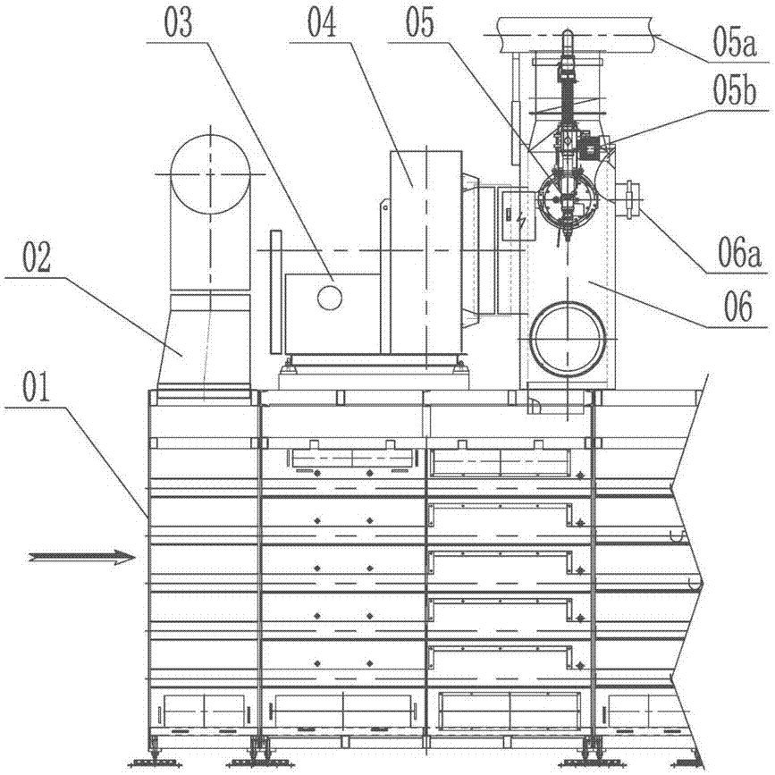
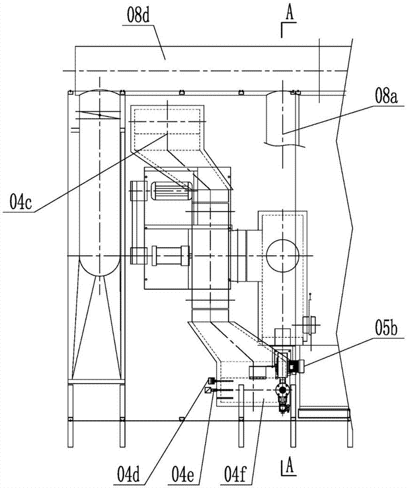
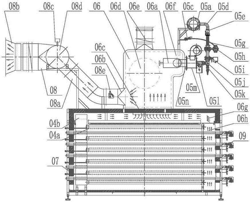
[0024] see Figure 1~3 , Figure 1~3 Shows the specific structure of the energy-saving drying kiln using ordinary air ducts as the combustion chamber of the present invention, which includes the drying kiln body 01, kiln head exhaust hood 02, heating system 04, combustion system 05, dehumidification system 08, heat preservation layer 07 and Transmission system 09; the drying kiln body 01 includes at least one standard modu...


PUM


Abstract

The invention discloses an energy-saving drying kiln using a common wind pipe as a combustion chamber. The energy-saving drying kiln comprises a drying kiln body, a heat supply system, a combustion system, a wet sucking system and a transmission system; the drying kiln body comprises at least one standard module section; each standard module section forms an independent circular heating system; the circular heating system comprises a square wind pipe; the square wind pipe is provided with a kiln afterheat inlet, a cold wind distribution port, a combustor connecting pipe, a heat supply outlet and a wet discharge port; the kiln afterheat inlet is connected with a kiln afterheat pipe; the cold wind distribution port is connected with the cold wind pipe; the combustor connecting pipe is connected with the combustion system; the heat supply outlet is connected with the heat supply system; hot wind combusted by the combustion system is mixed with kiln afterheat and cold wind by the circular heating system, and then, is fed above and below adobes in the transmission system through the heat supply system for drying; and dried moisture is discharged into atmosphere by the wet sucking system. The energy-saving drying kiln can realize effective drying of adobes to achieve the supply and sucking balance, and is more obvious in energy saving effect.

Description

technical field [0001] The invention relates to the technical field of ceramic drying, in particular to an energy-saving drying kiln using a common air duct as a combustion chamber. Background technique [0002] In the ceramic industry, when drying ceramic bodies, evaporation of water requires the absorption of a large amount of heat energy. If the kiln flue gas is used directly, the sulfur, dust and other substances in the kiln flue gas will cause damage to the environment and equipment; if only the waste heat of the kiln is used for cooling, the heat will be insufficient, so the burner is generally used to supplement the heat to reach the temperature required for drying. [0003] Due to the high temperature after the mixed combustion of fuel and air, traditional drying kilns generally use refractory and insulating bricks to build hot blast furnaces as combustion chambers, and then, the high-temperature flue gas after combustion is combined with a large amount of cold air ...

Claims


Application Information

Patent Timeline
IPC IPC(8): F26B15/02F26B23/00F26B21/08F26B23/02F26B21/00F26B25/00
CPCF26B15/02F26B21/001F26B21/08F26B23/002F26B23/02F26B25/00
Inventor 程希如陶志坚梁兴强郑旭东朱丙辉
Owner DLT TECH CO LTD
Why Eureka
Try Eureka