Hybrid beam forming iterative design method with low complexity
A hybrid beam, low-complexity technology, applied in the field of low-complexity hybrid beamforming iterative design, can solve problems such as difficulty in obtaining accurate original channel state information, and achieve the effects of reducing signaling overhead and cost
- Summary
- Abstract
- Description
- Claims
- Application Information
AI Technical Summary
Problems solved by technology
Method used
Image

Examples
Embodiment Construction
[0038] Below in conjunction with accompanying drawing, the present invention is described in further detail:
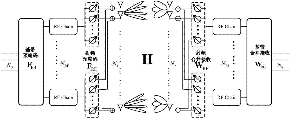
[0039] The main idea of the low-complexity hybrid beamforming iterative design scheme proposed by the present invention is to divide the hybrid beamforming design process into two stages of simulation. The first stage: iteratively design the analog precoding and analog combining receiving matrix at the receiving end; the first stage: after determining the analog precoding and analog combining receiving matrix, design the digital precoding and digital combining receiving matrix according to the equivalent channel in the digital domain .
[0040] The specific implementation plan is as follows:
[0041] Consider a downlink millimeter wave massive MIMO system, the base station uses N t root antenna, radio frequency transmission signal, the user uses N r root antenna, One radio frequency receiving signal, that is, both the transmitting and receiving ends adopt the...
PUM
 Abstract
Description
Claims
Application Information
PatSnap Eureka turns technology decisions into work you can execute. Powered by our Innovation Knowledge Graph, it runs expert workflows across engineering, life sciences, materials and intellectual property. Get your review-ready output in minutes.


